
Preparative Separation/Purification System

a separation/purification system and purification technology, applied in separation processes, filtration separation, instruments, etc., can solve the problems of reducing the time required for the vaporization and drying process, reducing and reducing the amount of emulsion collected in the collection container, so as to increase the collection efficiency of target components and reduce the amount of emulsion collected. the effect of increasing the collection efficiency of the target componen

Active Publication Date: 2011-08-18
SHIMADZU CORP
View PDF2 Cites 9 Cited by
  • Summary
  • Abstract
  • Description
  • Claims
  • Application Information

AI Technical Summary

Benefits of technology

[0009]In the separation / purification system disclosed in International Publication No. WO2009 / 044426, the second solvent, which has a low solubility to the first solvent, pushes up the first solvent. Although the second solvent and the first solvent are insoluble with each other, they partly form an emulsion around the interface between them. Since this emulsion contains the first solvent, in the system of International Publication No. WO2009 / 044426, the emulsion discharged from the upper end of the trap column is entirely disposed of, and only the second solvent is collected. This method can effectively prevent water from being included in the collection container, so that the eluate containing the target component is efficiently vaporized and dried.
[0010]However, the target compound which is captured by the adsorbent in the trap column also dissolves in the second solvent in the emulsion. That is, the emulsion that is discharged from the trap column also contains the target compound. Therefore, if the emulsion is completely disposed of, the collection efficiency will be decreased particularly in the case where the amount of the target compound collected in the trap column is small.
[0011]The present invention has been developed in view of the aforementioned problem, and the objective thereof is to provide a preparative separation / purification system for efficiently performing the process of vaporizing and drying the eluate containing a target compound, while enhancing the collection efficiency of the target compound by accelerating the initiation of collecting the eluate.

Problems solved by technology

According to the aforementioned method, however, a single vaporizing and drying process requires a long period of time of for example, several hours to one day.
Reducing the time required for the vaporizing and drying process is a critical issue since this process consumes, within the entire process, the longest period of time.
As compared to water, organic solvents have much lower boiling points and hence are highly volatile.
Therefore, when the target components are dissolved in a pure organic solvent, the vaporizing and drying process requires only a short period of time.
On the other hand, if water, which is less volatile, is included in the solvent, the vaporizing and drying process takes a considerably longer period of time.
This problem also arises in the widely used technique of introducing water into the passage of the mobile phase at a location before the trap column in order to dilute the mobile phase with water and thereby reduce the elution power of the mobile phase so that the target component can be assuredly captured.
When such a large amount of water is present in the trap column, supplying an organic solvent into the trap column to elute the target component will naturally result in a large amount of remnant water to be included in the solution exiting from the trap column.
If both water and an organic solvent are contained in the collected solution, a long period of time is required to vaporize the water, and what is worse, the water overlies the organic solvent stored in the collection container as a cover, which prevents the organic solvent from evaporating.

Method used


Image

  • Preparative Separation/Purification System
  • Preparative Separation/Purification System
  • Preparative Separation/Purification System

Examples


Embodiment Construction

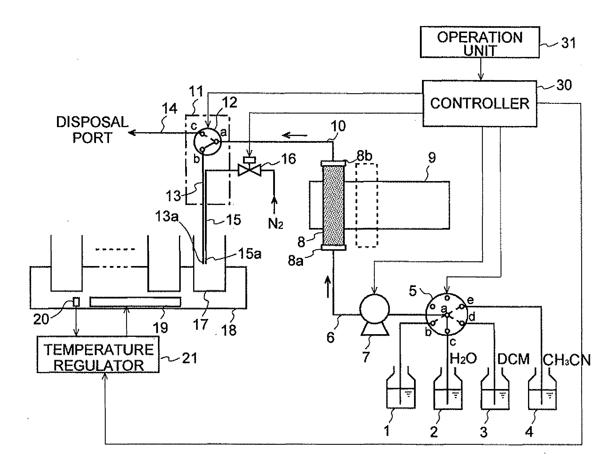
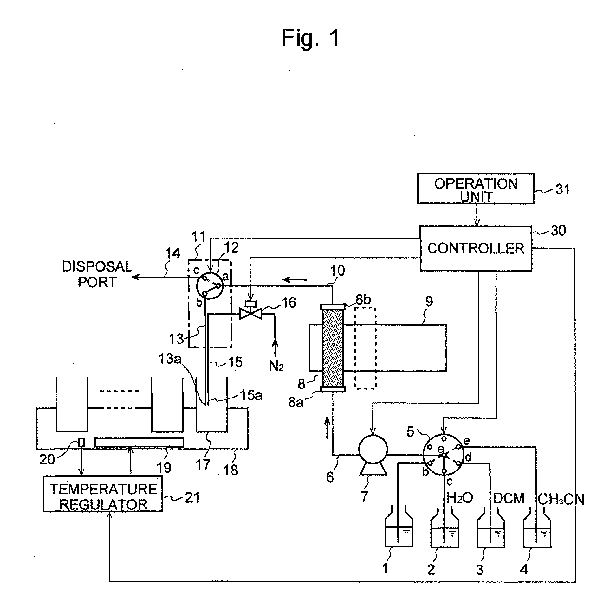
[0079]An embodiment of the preparative separation / purification system according to the present invention will be described with reference to FIGS. 1 through 5.

[0080]FIG. 1 is a schematic configuration diagram of the preparative separation / purification system of the present embodiment. In FIG. 1, a mobile phase with the target compound dissolved therein is contained in a solution container 1. A wash water container 2 holds pure water acting as the first solvent of the present invention. An eluting solvent container 3 holds dichloromethane / methanol mixture (hereinafter, which will be simply referred to as “dichloromethane” and which is labeled as “DCM” in the figure) acting as the second solvent of the present invention. A wash solution container 4 holds acetonitrile acting as the third solvent of the present invention. A selector valve 5 is provided to change the passage configuration so that one of the liquids held in these containers 1 through 4 is selectively supplied to a supply ...


PUM

PropertyMeasurementUnit
Timeaaaaaaaaaa
Flow rateaaaaaaaaaa
Volumeaaaaaaaaaa

Abstract

The present invention aims at providing a preparative separation / purification system for vaporizing an eluate in a short period of time, while enhancing the efficiency of collecting the target substance by accelerating the initiation of collecting the eluate. The preparative separation / purification system in which water containing a target component is passed through a column 8 to capture the target component in the column 8 and then a solvent is passed through it to collect the target compound, includes: a liquid supply means 7 for supplying a solvent to the column 8, with the target component captured in the column 8, while the column 8 is vertically held with the inlet end thereof directed downwards and the discharge end thereof directed upwards, the solvent having a low solubility to water and having a specific gravity greater than that of water; a passage selection means 12 for changing the passage configuration so that a solution exiting from the column 8 is selectively sent to either a collection passage 13 or a disposal passage 14; a passage control means 30 for controlling the passage selection means 12 so that, when water exits from the column 8, the water is sent to the disposal passage 14, and when solution containing solvent exits from the column 8, the solution is sent to the collection passage 13; and a flow rate control means 30 for controlling so that the water is supplied at a first flow rate to the disposal passage 14, and the solution containing solvent is supplied to the collection passage 13 at a flow rate lower than the first flow rate.

Description

[0001]The present invention relates to a preparative separation / purification system for separately extracting one or more components from a solution by a liquid chromatograph, and purifying and collecting the components in solid forms.BACKGROUND OF THE INVENTION[0002]Conventionally, in the pharmaceutical industry and other fields, preparative separation / purification systems utilizing chromatographs are used to analyze synthesized compounds or store them in a library (Refer to Japanese Unexamined Patent Application Publication No. H02-122260).[0003]In these apparatuses, target components (compounds) in a sample solution are temporally separated by a liquid chromatograph. The separated target components are then respectively introduced into different trap columns and temporarily captured therein. Subsequently, a solvent is supplied into each trap column to quickly elute the component from the trap column and collect it in a container. Thus, a plurality of solutions each containing one...

Claims


Application Information

Patent Timeline
IPC IPC(8): B01D15/08
CPCB01D15/163G01N2030/8494B01D15/247G01N30/08G01N30/20G01N30/26G01N30/32G01N30/34G01N30/462G01N30/80G01N30/82G01N2030/085G01N2030/202G01N2030/8411G01N2030/8429B01D15/166
Inventor YAMAZAKI, TOMOYUKI
Owner SHIMADZU CORP
Learn More