
Hydrodynamic torque converter

Active Publication Date: 2011-08-11
SCHAEFFLER TECH AG & CO KG
View PDF3 Cites 57 Cited by
  • Summary
  • Abstract
  • Description
  • Claims
  • Application Information

AI Technical Summary

Benefits of technology

Object of the invention is a torque converter with corresponding vibration insulation, in which a centrifugal force pendulum is not exposed or only exposed in a reduced manner, to pendulum knocks, and / or the design of the centrifugal force pendulum is simplified under such conditions, for instance, the vibration angle of the centrifugal force pendulum is reduced.
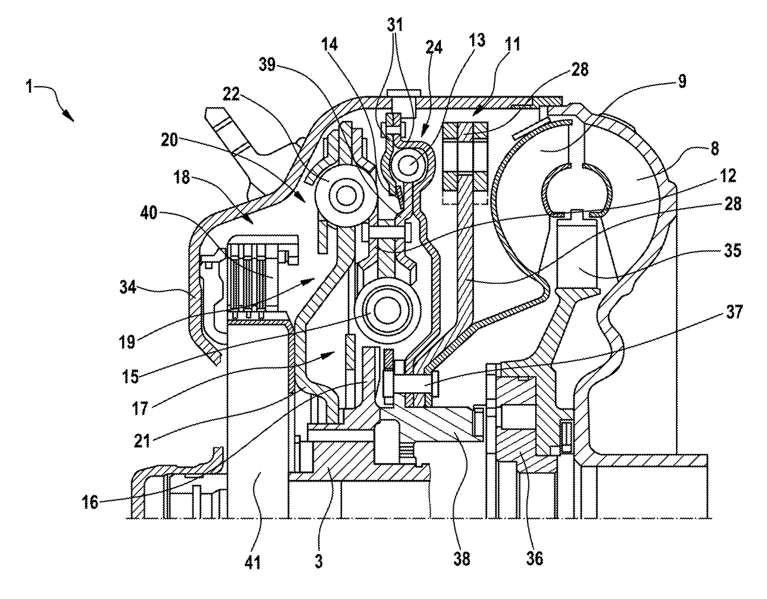
The object is met by a hydrodynamic torque converter with a turbine driven by an impeller and connected with a output part as well as housing, in which a torsional vibration damper with several damper stages and a torsional vibration absorber as well as housing and lock-up clutch connecting the output part are installed additionally. The torsional vibration absorber is connected with the turbine and is formed by a centrifugal force pendulum and a turbine absorber. By dividing the torsional vibration absorber into a turbine absorber and a centrifugal force pendulum, improvement of vibration insulation is achieved, in that by connecting the turbine absorber in the torque path upstream of the centrifugal force pendulum, the latter can be tuned to a smaller vibration angle in a less complex manner. Thus, for instance, vibration angles of the pendulum masses relative to the disk part carrying them can be made smaller than 40°, without them knocking on the disk part under normal operating conditions of a drive train, for instance, in connection with a 4-cylinder diesel engine.
In the closed state of the lock-up clutch, the torque from the housing is fed via the lock-up clutch into the first damper stage of the torsional vibration damper and from there into the output part of the transmission input shaft. Through the linkage of the turbine absorber to the intermediate part of both damper stages, the turbine absorber couples to the clutch damper by means of its flange parts, whereby the turbine connected to the cover plate serves as an absorber mass. Thereby, hydrodynamic effects, particularly the blades of the turbine contribute additional moments of inertia. The centrifugal force pendulum, for example, coupled with the turbine is thereby only exposed to the vibration angles—not yet absorbed—by the turbine absorber and can be dimensioned accordingly for a smaller vibration angle.

Problems solved by technology

Such an arrangement of damping units may not be adequate in internal combustion engines of the above-mentioned type, so that pendulum weights on the centrifugal force pendulum are possible.
The design of the centrifugal force pendulum can therefore be difficult, particularly at low speeds with high swivel angles of the internal combustion engine.
Limit stops of pendulum weights or masses act, particularly, on the drive train of a motor vehicle, through a humming sound that causes discomfort.

Method used


Image

  • Hydrodynamic torque converter
  • Hydrodynamic torque converter
  • Hydrodynamic torque converter

Examples


Embodiment Construction

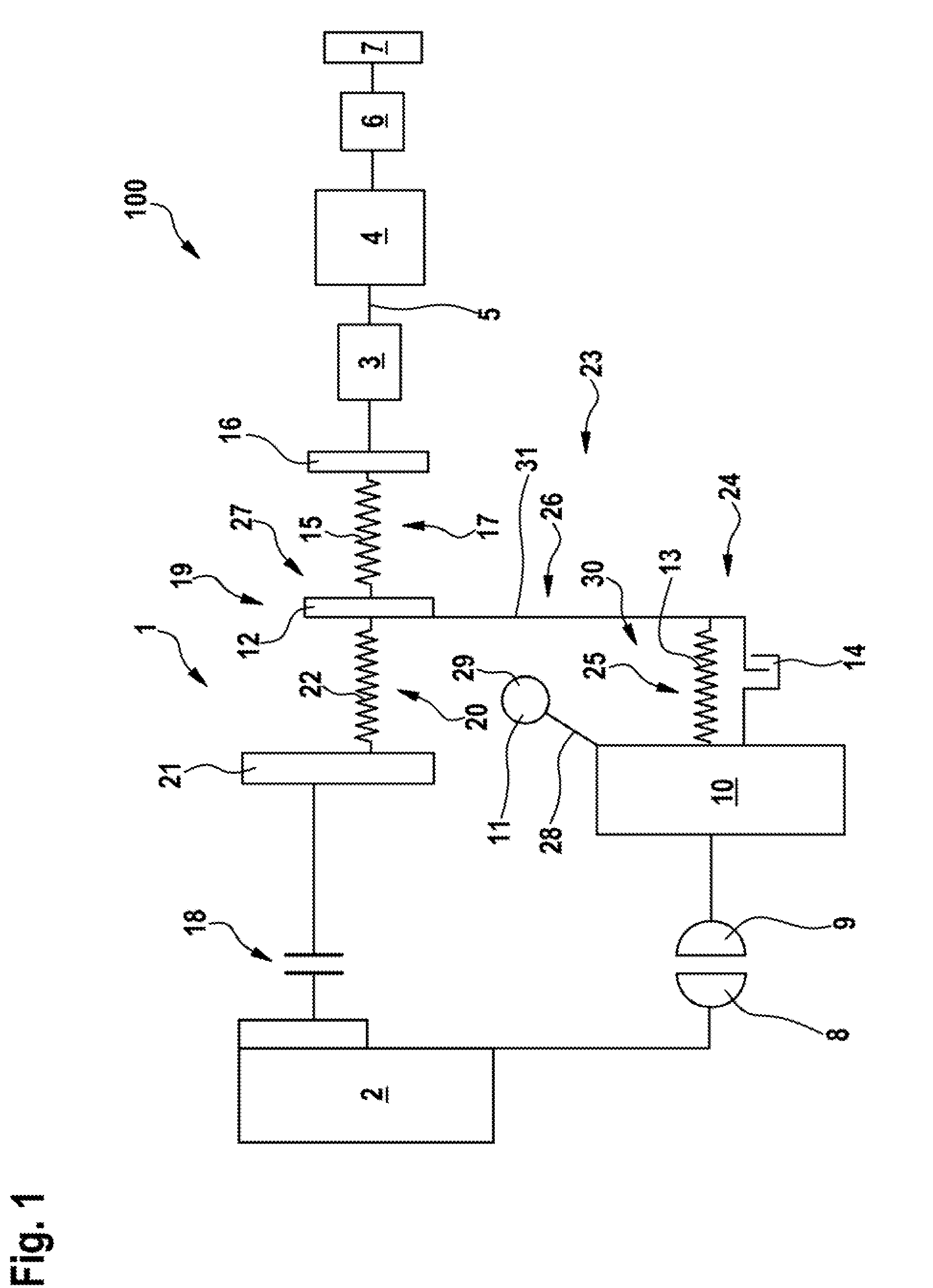
FIG. 1 shows a schematically depicted prototype of a drive train 100 in a motor vehicle with a hydrodynamic torque converter 1, which is driven by an internal combustion engine 2, for instance, a 4-cylinder diesel engine. Torque is transmitted by the engine and possibly converted via an output part 3 to a transmission input shaft 5 belonging to the transmission 4. In the transmission 4, which can be an automated manual transmission, an automated gearshift stages or a continuously variable transmission, like toroidal or chain CVT, the transmission ratios are set corresponding to the driving states of the vehicle and the driving torque transmitted via a differential unit 6 to at least a drive wheel 7.

The torque converter 1 serves as a starting- and torque transmission element and provides two torque paths for the transmission of torque loaded with torsional-vibration, provided by the internal combustion engine 2. The one torque path is established through the hydrodynamic transmission...


PUM


Abstract

A hydrodynamic torque converter (1), comprising a turbine wheel (9) driven by an impeller (8) and connected to an output part, and comprising a housing (34), in which a torsional vibration damper (19) having several damper stages (17, 20) and a centrifugal force pendulum (11), and also a converter lockup clutch (18) connecting a housing and an output part (3), are accommodated. In order to avoid any striking of the pendulum masses of the centrifugal force pendulum in internal combustion engines having large oscillating angles driving the torque converter, a turbine damper is connected in the power flow upstream of the centrifugal force pendulum.

Description

CROSS-REFERENCE TO RELATED APPLICATIONSThis application is filed under 35 U.S.C. §120 and §365(c) as a continuation of International Patent Application No. PCT / DE2009 / 001342, filed on Sep. 24, 2009, which application claims priority from German Patent Application No. 10 2008 051 972.3, filed on Oct. 16, 2008, which applications are incorporated herein by reference in their entirety.FIELD OF THE INVENTIONThe invention relates to a hydrodynamic torque converter with an impeller, a turbine, a lock-up clutch as well as a torsional vibration damper and a torsional vibration absorber.BACKGROUND OF THE INVENTIONTorque converters are familiar in drive trains of motor vehicles and are preferably disposed between an internal combustion engine and a transmission. Thereby, the converter's function with excessive torque increase is preferably utilized for starting the motor vehicle, in that the torque from the housing that is driven by the internal combustion engine is transmitted via the impell...

Claims


Application Information

Patent Timeline
IPC IPC(8): F16H45/02
CPCF16F15/12353F16F15/145F16H45/02F16H2045/007F16H2045/0284F16H2045/0226F16H2045/0231F16H2045/0263F16H2045/021
Inventor WERNER, MARKUSLOXTERMANN, JAN
Owner SCHAEFFLER TECH AG & CO KG
Learn More