
Ridge Vent and Roof Ridge Assembly

a technology of roof ridge and ridge vent, which is applied in ventilation systems, lighting and heating apparatus, heating types, etc., can solve the problems of unreasonable cooling energy requirements and uncomfortable living quarters of buildings

Active Publication Date: 2011-08-04
BENJAMIN OBDIKE +1
View PDF37 Cites 21 Cited by
  • Summary
  • Abstract
  • Description
  • Claims
  • Application Information

AI Technical Summary

Benefits of technology

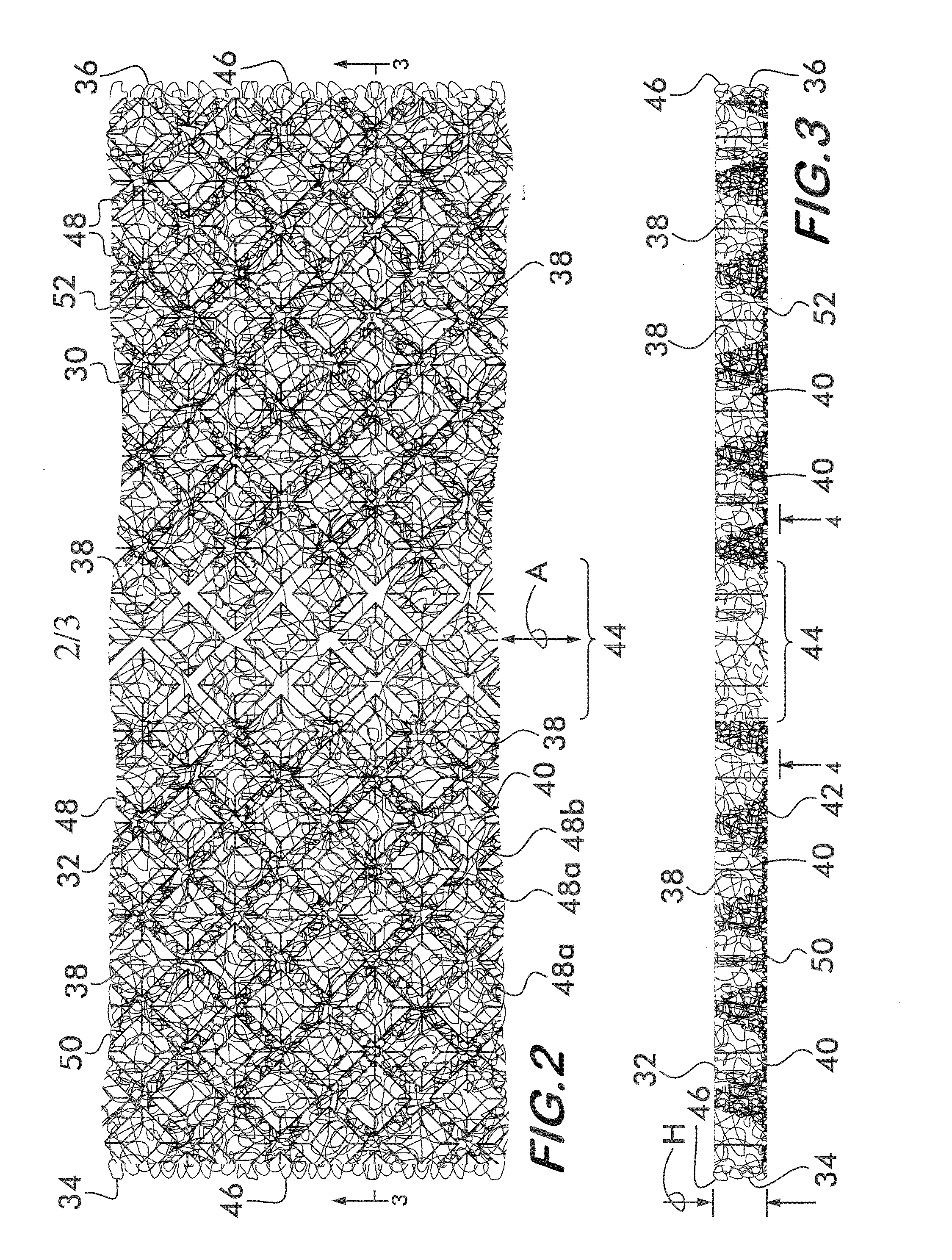
[0006]According to a most economical embodiment of the present invention, the roof ridge vent consists solely of the mat without any dissimilar materials laminated thereto. For example, the mat can consist solely of melt-spun thermoplastic polymeric filaments extruded in overlapping, irregularly-looped patterns with the polymeric filaments being self-bonded and fused at random points of intersection without bonding agents or inserts. The side edges of the mat can be formed by looped uncut sections of the filaments and thus do not even require trimming operations during manufacture of the vent. As an alternative, one or both side edges can be subjected to a trimming, cutting, slitting or like operation.
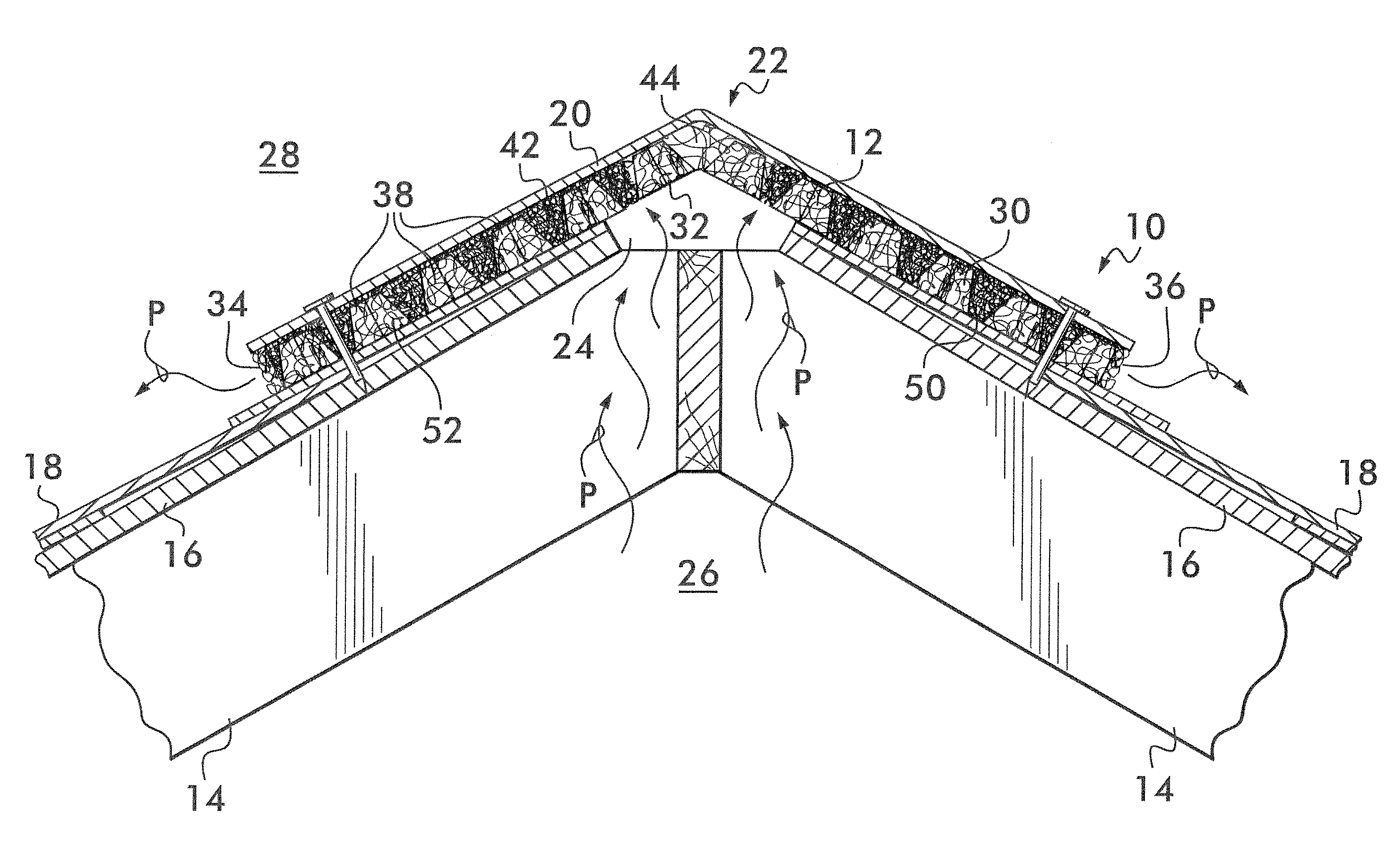
[0008]The mat includes a central longitudinally-extending hinge portion and opposite laterally-extending flap portions extending from opposite sides of the hinge portion. The hinge portion is flexible and permits the mat to conform to an inverted-V shape of an underlying roof ridge. The grid pattern of recesses and the latticework structure of upstanding openwork walls preferably extend uniformly and uninterrupted throughout the flap portions and across the hinge portion. In at least some contemplated embodiments, a density of convoluted polymeric filaments within the hinge portion can be less than a density of convoluted polymeric filaments in the opposite laterally-extending flap portions to provide the hinge portion with flexibility.

Problems solved by technology

Such ventilation prevents undue heat buildup, which can render the living quarters of the building uncomfortable and impose unreasonable energy requirements for cooling.

Method used


Image

  • Ridge Vent and Roof Ridge Assembly
  • Ridge Vent and Roof Ridge Assembly
  • Ridge Vent and Roof Ridge Assembly

Examples


Embodiment Construction

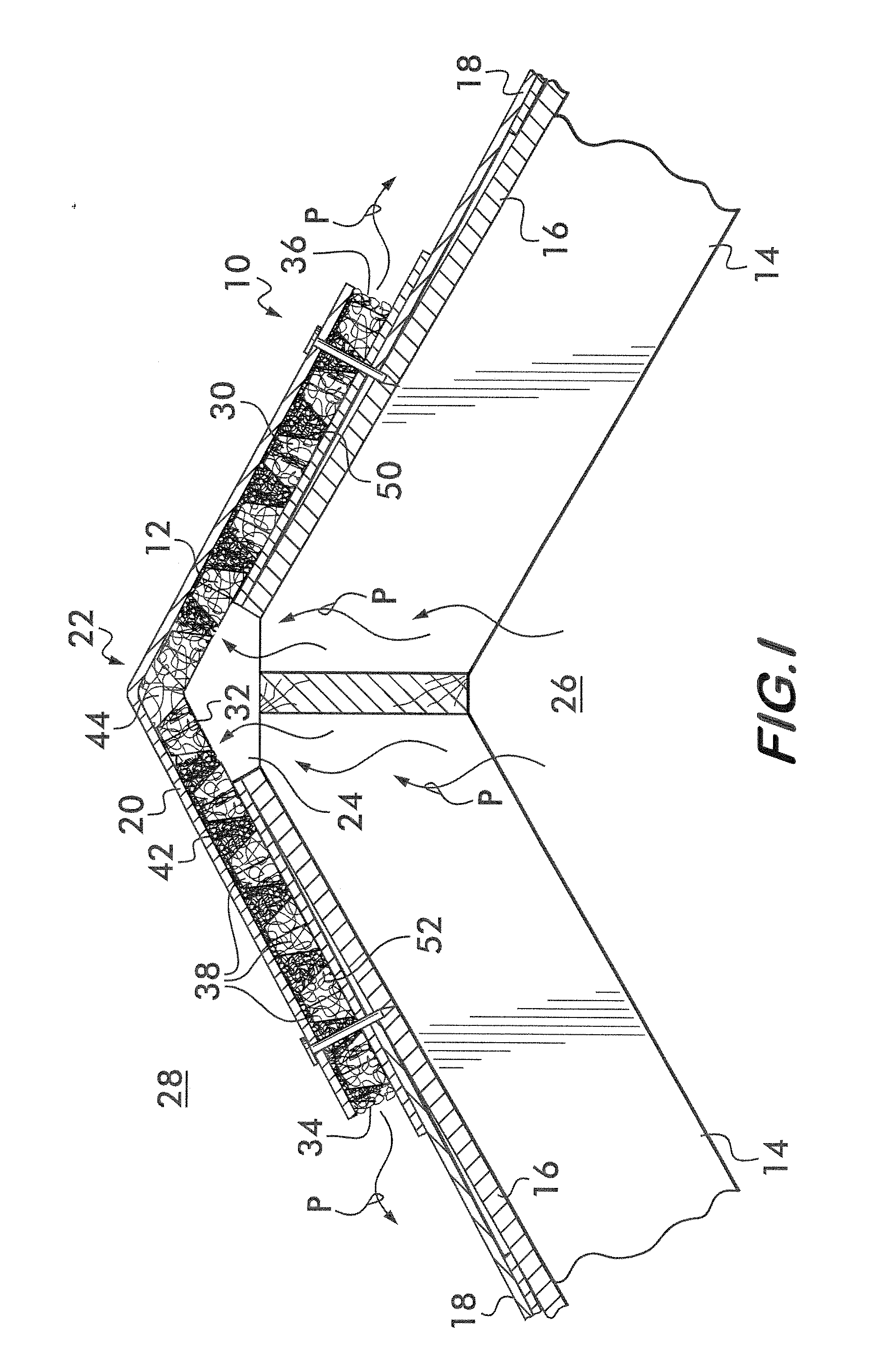
[0016]FIG. 1 illustrates a roof 10 having a typical construction which utilizes a roof ridge vent 12. The roof 10 is constructed from a plurality of rafters 14 supported at their lower ends, for instance, by front and rear walls (not shown) of the building. A roof deck 16 is typically constructed of plywood, or other suitable panels, to provide an outer sheathing of the building. The roof deck 16 is secured to the rafters 14 and extends to the end walls. Shingles 18 or other exterior coverings are secured to the roof deck 16 to finish sloping portions of the roof 10 in accordance with conventional construction practices. Cap shingles 20 or like coverings are installed in overlapping fashion to cover the roof ridge or peak 22. One or more continuous or discontinuous slots 24 are provided along the length of the roof ridge 22 to provide a passageway for venting air between the underlying attic area 26 and ambient atmosphere 28.

[0017]The ridge vent 12 is interposed between the cap shin...


PUM


Abstract

A roof ridge vent for installation overlying an open roof ridge to provide ventilation to a space beneath a roof is provided. The ridge vent is a continuous, elongate mat of randomly convoluted polymeric filaments having an openwork upper face, an openwork opposite lower face, a plurality of hollow recesses extending into the mat and opening into the lower face, and opposite longitudinally-extending openwork side edges. The openwork upper face is formed of randomly convoluted filaments formed to provide a relatively flat surface of sufficient density to catch heads of fasteners. The plurality of hollow recesses is defined by a plurality of upstanding openwork walls of convoluted filaments that extend from the upper face to the lower face of the mat. The upstanding openwork walls are arranged in a latticework structure such that no unobstructed passageways extend through the mat through which wind-blown rain and snow can freely pass into the side edges of the mat and laterally pass through the mat. A ventilated roof ridge assembly including the vent is provided.

Description

BACKGROUND OF THE INVENTION[0001]The present invention relates to a roof ridge vent for enhancing the circulation of air in a space between a roof and an underlying structure.[0002]It is useful, and in many locales a building code requirement, that the attic area of a building be provided with a means to permit air exchange. Such ventilation prevents undue heat buildup, which can render the living quarters of the building uncomfortable and impose unreasonable energy requirements for cooling. Proper ventilation of the attic area also tends to preserve the structural integrity of the roof and roof coverings.[0003]One known method of venting consists of applying a venting media over a ventilation slot cut along the ridge of a roof. This type of vent is referred to as a ridge vent. Examples of roof ridge vents are disclosed by U.S. Patent Application Publication No. 2008 / 0220714 of Caruso et al. and U.S. Pat. Nos. 4,942,699 issued to Spinelli; 5,960,595 issued to McCorsley et al.; 5,673...

Claims


Application Information

Patent Timeline
IPC IPC(8): F24F7/02E04D13/17
CPCF24F7/02E04D13/17E04D13/172E04D13/176E04D13/174
Inventor KERWOOD-WINSLOW, TEDCARUSO, GEORGECOULTON, MICHAEL S.HASCHER, LORI CURTISSMATHIS, II, JAMES EMORYDENTON, JEFFREY SCOTT
Owner BENJAMIN OBDIKE
Learn More