Gas-blanketed piping connections

a technology of gas-blank piping and piping connections, which is applied in the direction of sealing/packing, mechanical equipment, and well accessories, etc., can solve the problems of affecting the service life of the pipeline, the risk of explosion, and the negative pressure of the pipeline, so as to achieve the effect of beneficial and advantageous

Inactive Publication Date: 2011-08-04
OPTIMUM PROD TECH INC
View PDF16 Cites 19 Cited by
  • Summary
  • Abstract
  • Description
  • Claims
  • Application Information

AI Technical Summary

Benefits of technology

[0013]In accordance with one embodiment of the present invention, the inward migration of air through a bolted flanged connection, and into a vessel or piping containing a flammable gas under negative pressure, may be prevented by providing double seal means between the mating faces of the two flanges being connected, with the double seal means being configured to form an annular chamber into which a blanketing gas is introduced, at a pressure higher than atmospheric.
[0025]In a third aspect, the present invention teaches a method of providing enhanced protection against migration of gas through a connection between two fluid-carrying pipes, said method comprising the steps of providing primary and secondary seals extending around the connection, said primary and secondary seals being spaced apart, and each of said primary and secondary seal means providing a seal between the first and second pipes; providing an annular chamber extending around the circumference of the male end of the second pipe, said annular chamber being disposed between the primary and secondary seals; and providing a gas inlet channel in fluid communication with the annular chamber and with a source of a blanketing gas, such that blanketing gas can flow through the gas inlet channel into the annular chamber.

Problems solved by technology

However, negative pressure in a natural gas pipeline would present an inherent problem, because any leak in the line (such as at pipeline joints) would allow the entry of air into the pipeline, because air would naturally flow to the area of lower pressure.
This would create a risk of explosion should the air / gas mixture be exposed to a source of ignition.
In addition to the explosion risk, entry of air into the pipeline also creates or increases the risk of corrosion inside the pipeline.
The explosion and corrosion risks are thus minimized or eliminated, but in a way that effectively limits ultimate recovery of as reserves from the well.
However, this system has an inherent drawback in that its effectiveness would rely on the proper functioning of the oxygen sensor.
If the sensor malfunctions, and if the malfunction is not detected and remedied in timely fashion, the risk of explosion and / or corrosion will become manifest once again.
This fact highlights an even more significant drawback in that this system would not prevent the influx of air into the pipeline in the first place, but is merely directed to mitigation in the event of that undesirable event.
Should such a leak occur, there would merely be a harmless transfer of gas from the positive pressure jacket into the intake pipeline.
Should a leak develop in the positive pressure jacket, any gas leaking therefrom would escape into the atmosphere, and entry of air into the positive pressure jacket would be impossible.
If effective protection against air influx can be provided at flanged connections, it may be unnecessary to provide complete or even partial positive pressure gas jacketing.
However, there are no perfect or foolproof gaskets, and fugitive emissions of gas through gasketed flanged connections are a common reality.
This might not be desirable from an environmental standpoint, but it does not create a fire or explosion hazard.
In this situation, deficiencies or defects in the gaskets can result in the higher-pressure air leaking into the stream of flowing gas (or into non-flowing gas in a storage vessel), thereby causing a serious hazard even when only small volumes of air are involved.
For this reason, gasketing technology per se cannot be relied on to provide an acceptable solution to the problem of air leakage through bolted flanged connections into conduits or vessels containing flammable gas under negative pressure.

Method used


Image

  • Gas-blanketed piping connections
  • Gas-blanketed piping connections
  • Gas-blanketed piping connections

Examples


Embodiment Construction

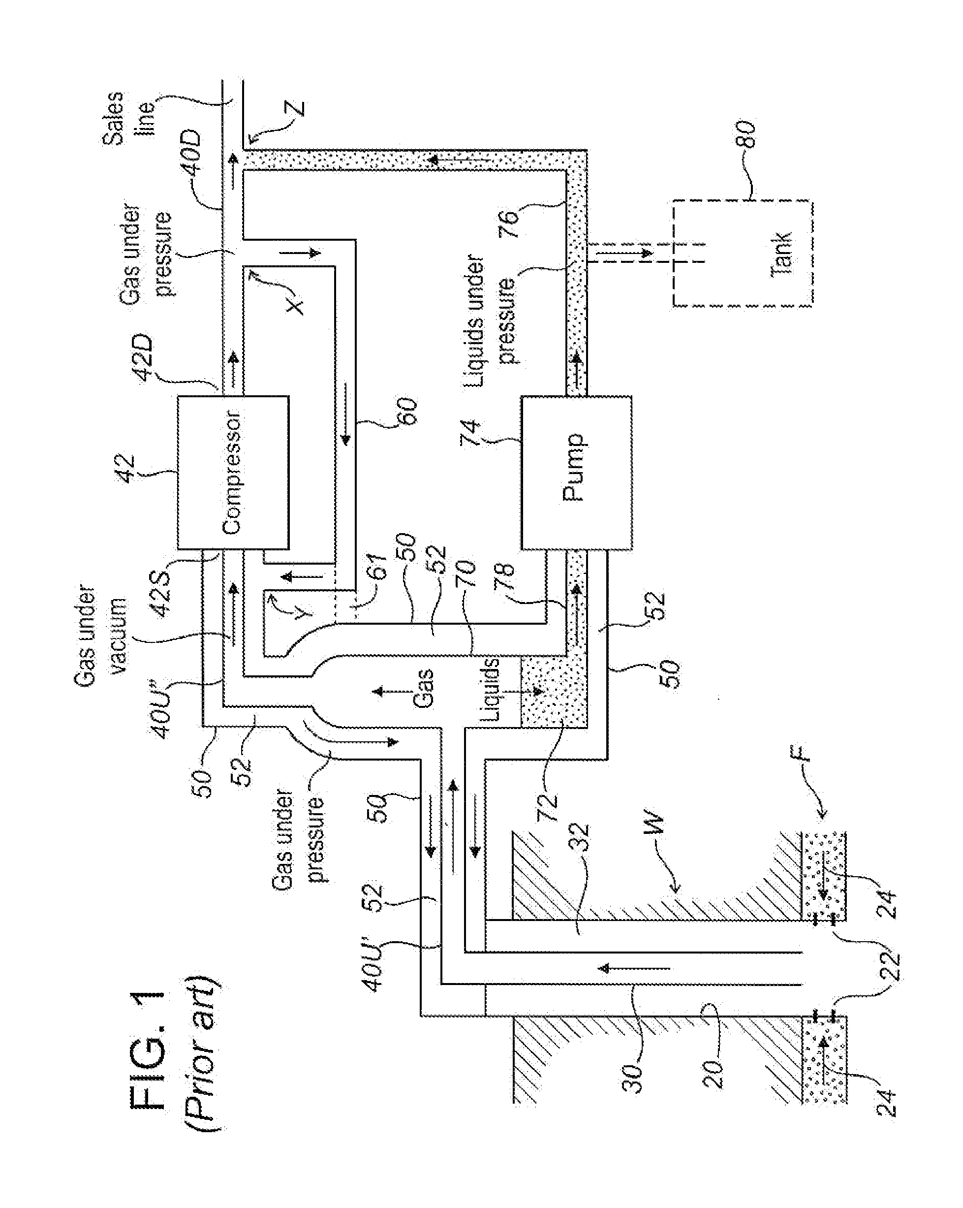
[0032]The present invention will be best understood after first reviewing methods and apparatus taught by CA 2,536,496 and U.S. Pat. No. 7,275,599 for protecting against air influx into piping and equipment components conveying or containing gas under negative pressure. FIG. 1 (which is not to scale) schematically illustrates a typical natural gas well W penetrating a subsurface formation F containing natural gas. Well W is lined with a casing 20 which has a number of perforations conceptually illustrated by short lines 22 within a production zone (generally corresponding to the portion of the well penetrating the formation F). As conceptually indicated by arrows 24, formation fluids including gas, oil, and water may flow into the well through the perforations 22. A string of tubing 30 extends inside the casing 20, terminating at a point within the production zone. The bottom end of the tubing 30 is open such that fluids in the wellbore may freely enter the tubing 30. An annulus 32 ...


PUM


Abstract

Migration of air through a flanged connection into piping containing a gas under negative pressure is prevented by disposing concentric inner and outer gaskets between the flange faces, so as to form an annular chamber into which a blanketing gas is introduced at a pressure higher than atmospheric. Air tending to migrate through the outer gasket is blocked by the higher-pressure blanketing gas in the annular chamber. The blanketing gas pressure is maintained at a level higher than atmospheric notwithstanding any fugitive emissions through the outer gasket. The annular chambers of multiple flanged connections may be interconnected to blanket multiple flanged connections using a single source of blanketing gas. The blanketing gas may be the same type as the gas under negative pressure. In sour service applications, an inert blanketing gas may be used to prevent leakage of sour gas to atmosphere through flanged connections. In alternative embodiments, the principles of the invention may be adapted for use with other types of connections including threaded piping connections, and for use with piping carrying liquids.

Description

FIELD OF THE INVENTION[0001]The present invention relates to methods and apparatus for protecting against the influx of air into piping carrying a combustible gas under negative pressure, and particularly to such methods and apparatus for protecting against such influx of air at flanged and threaded piping connections.BACKGROUND OF THE INVENTION[0002]Natural gas is commonly found in subsurface geological formations such as deposits of granular material (e.g., sand or gravel) or porous rock. Production of natural gas from these types of formations typically involves drilling a well a desired depth into the formation, installing a casing in the wellbore (to keep the well bore from sloughing and collapsing), perforating the casing in the production zone (i.e., the portion of the well that penetrates the gas-bearing formation) so that gas can flow into the casing, and installing a string of tubing inside the casing down to the production zone. Gas can then be made to flow up to the surf...

Claims


Application Information

Patent Timeline
Patent Type & Authority Applications(United States)
IPC IPC(8): E21B19/16F16L23/00
CPCE21B43/12E21B33/02
Inventor WILDE, GLENN
Owner OPTIMUM PROD TECH INC
Why Eureka
Try Eureka