
Cast iron or aluminum sectional boiler

a sectional boiler and aluminum technology, applied in the direction of water heaters, furnace-tube steam boilers, sustainable buildings, etc., can solve the problems of less favorable scaling conditions, high material cost, and difficult assembly in confined spaces, and achieve compactness and robustness, good thermal transfer properties, and high efficiency.

Inactive Publication Date: 2011-08-04
ROBERT BOSCH GMBH
View PDF12 Cites 4 Cited by
  • Summary
  • Abstract
  • Description
  • Claims
  • Application Information

AI Technical Summary

Benefits of technology

[0010]An object of the present invention is to optimize a cast iron or aluminum sectional boiler, in particular with respect to compactness and robustness.
[0022]The present invention creates a sectional boiler optimally suitable for a condensing boiler operation, the positive material properties of cast iron or aluminum being specifically applied and utilized to ensure good thermal transfer properties, compactness, and robustness. Corrosion-inducing exposures are brought under control. According to the present invention, the corrosion-resistant coating itself is not only easy to apply and control, it is also protected against possible mechanical stresses in the gaps.
[0023]The division of the water and heating gas side into a primary and a secondary section results in an intensive heat exchange which is optimally adjusted to the temperatures prevailing in the particular areas. This results in very high efficiency without an increase of the complexity of the components and without limitations in cleaning properties.
[0024]In addition to simple manufacturing, the design of the sections offers the advantage that it is possible to variably adjust for different firing capacities and heat exchanger outputs by inserting additional center sections of varying lengths. Nonetheless, all attachment components situated preferably on the face part and all water-side connections remain the same. Only the jacket surrounding the flue gas collection chamber varies. Due to the low flue gas temperatures, the flue gas collection chamber may even be manufactured from plastic.

Problems solved by technology

Disadvantages are the high costs associated with the material as well as the less favorable scaling conditions in particular in welded sheet metal constructions and the larger physical sizes which make assembly difficult in confined spaces.
All boilers having a downstream heat exchanger have the disadvantages that the assembly expense is increased by the necessary pipe components and resistance on the water side rises.
As a separate, external component, the system also causes cooling losses which must be reduced by suitable thermal insulation.

Method used


Image

  • Cast iron or aluminum sectional boiler
  • Cast iron or aluminum sectional boiler
  • Cast iron or aluminum sectional boiler

Examples


Embodiment Construction

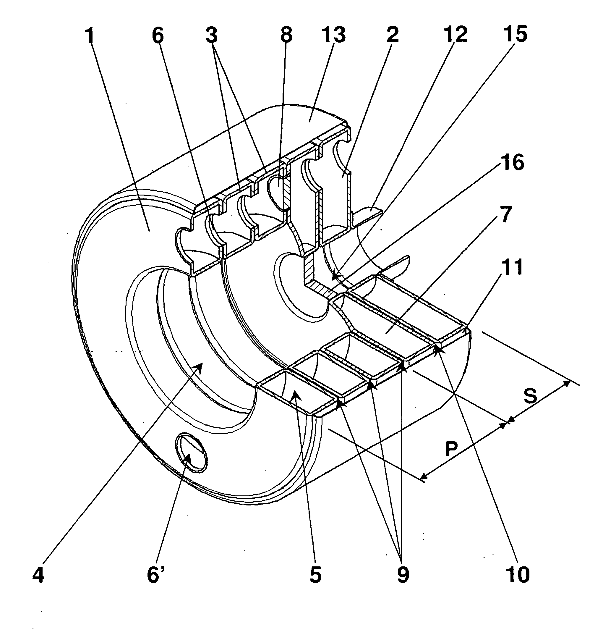
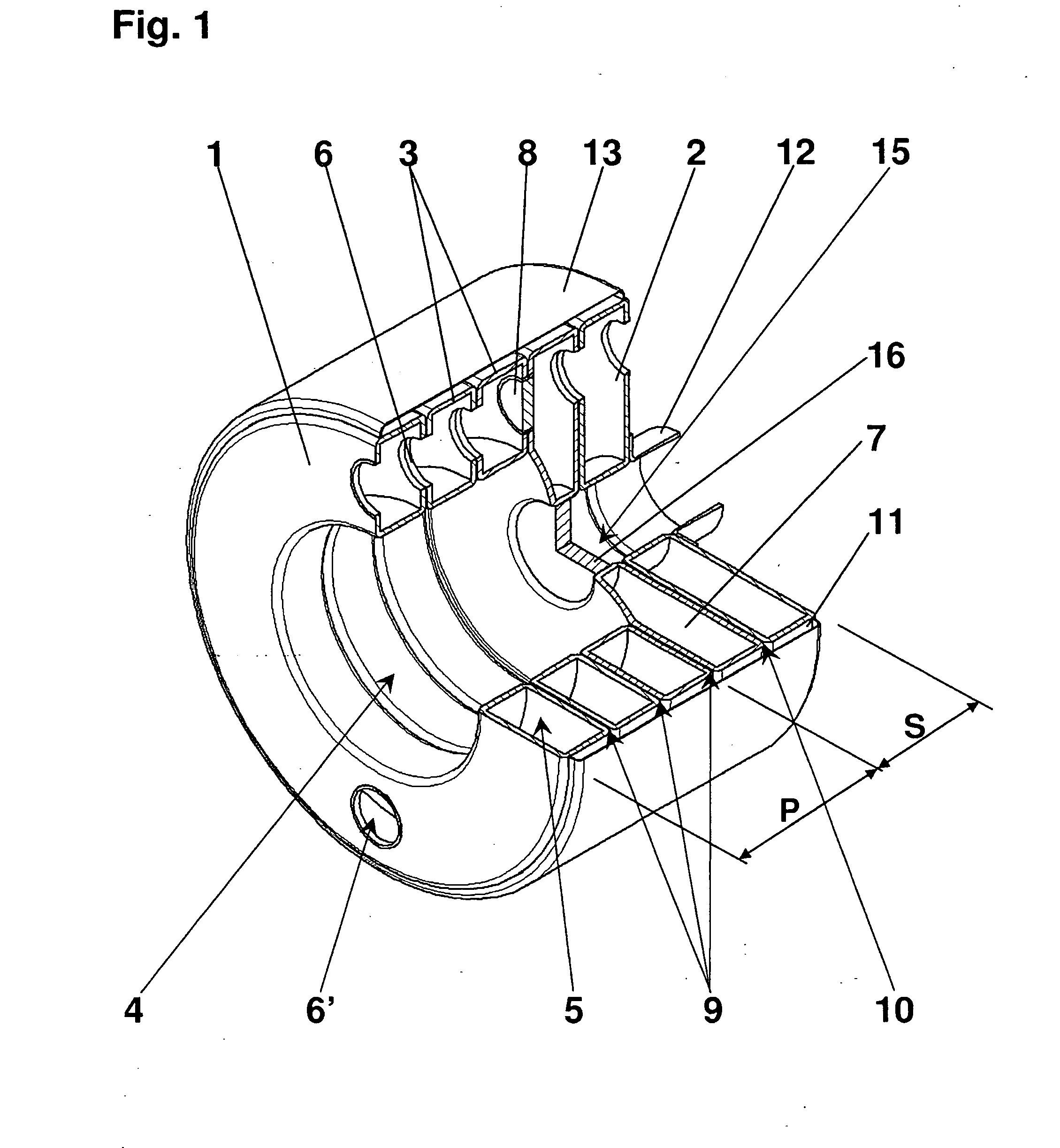
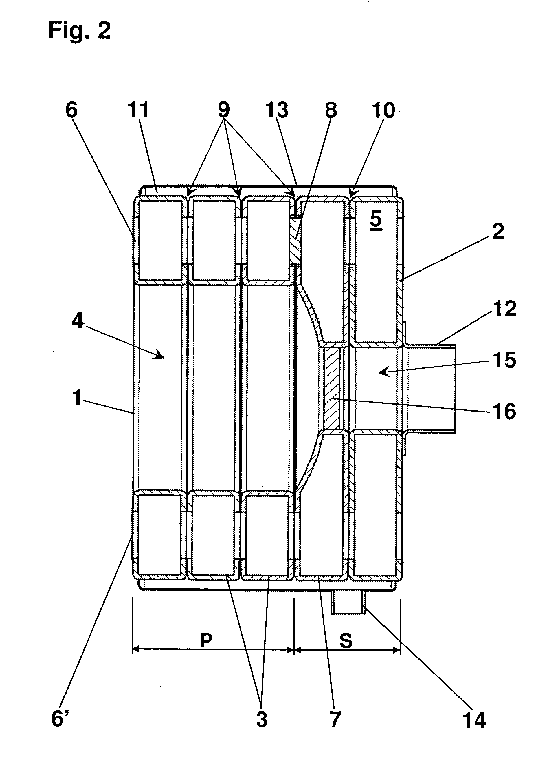
[0028]The sectional boiler is essentially made up of annular sections, namely a front section 1, a cover-like rear section 2, and a plurality of center sections 3. These sections constitute a furnace chamber 4 and their annular water compartments 5 are connected to one another via hubs 6, 6′.

[0029]According to the present invention, the heating gas passages are subdivided into a primary section P and a secondary section S. A furnace chamber floor center section 7 is additionally provided for this purpose. Together with front section 1 and at least one center section 3, this furnace chamber floor section forms furnace chamber 4 and limits its depth. Front section 1 and at least one center section 3 are thus part of the primary section on the water and heating gas side, while rear section 2 and furnace chamber floor center section 7 form the secondary section at least on the water side. To that end, at least one hub 6, 6′ is closed between furnace chamber floor center section 7 and ad...


PUM


Abstract

A cast iron or aluminum sectional boiler has essentially annular sections, one front section, one rear section and at least one center section being provided which form a furnace chamber having essentially surrounding heating gas passages, and their annular water compartments are connected to one another via hubs. The sections have one return connection piece and one feed connection piece, one flue spigot as well as at least two anchor rods for holding the section block together. Annular gaps are provided as heating gas passages between each two adjacent sections, and that the heating gas passages are subdivided into a primary section and a secondary section.

Description

BACKGROUND OF THE INVENTION[0001]1. Field of the Invention[0002]The present invention relates to a cast iron or aluminum sectional boiler, in particular a condensing boiler.[0003]2. Description of Related Art[0004]Sectional boilers of this type are made up of a plurality of boiler sections cast in one piece which are situated one behind the other and connected to one another by hubs on the water side. Flow takes place through the water channels and water pockets formed by the boiler sections between the return connection and the feed connection. Sectional boilers according to the definition of the species generally have a lower return connection and a feed connection situated at the top, preferably in the particular hub. The heating gases overflow from the furnace chamber via downstream heating gas passages to a flue spigot and transmit heat to the boiler water on their way.[0005]In all previous boilers of this type, the sections are situated in series one behind the other. There is...

Claims


Application Information

Patent Timeline
IPC IPC(8): F22B7/00
CPCF24H1/32F24H8/00Y02B30/102F24H9/0042F24H9/0015Y02B30/00
Inventor RAUSCH, RAINERJUNG, GERHARDHENRICH, HOLGER
Owner ROBERT BOSCH GMBH
Learn More