
System for monitoring plant equipment

Active Publication Date: 2011-07-28
HOLCIM US
View PDF18 Cites 101 Cited by
  • Summary
  • Abstract
  • Description
  • Claims
  • Application Information

AI Technical Summary

Benefits of technology

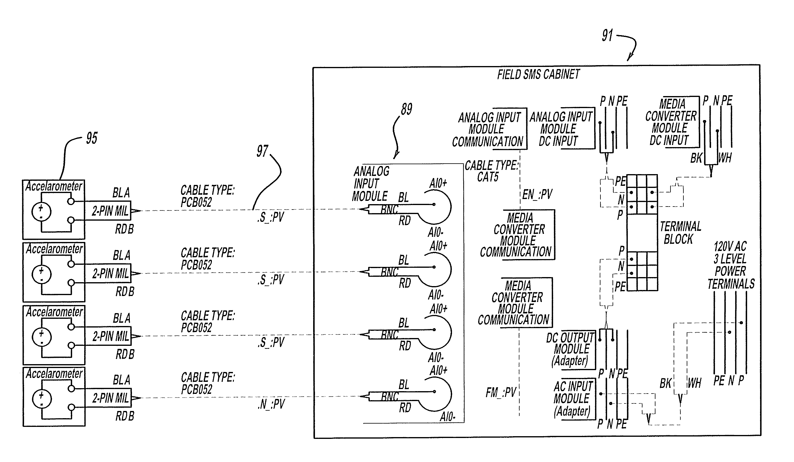
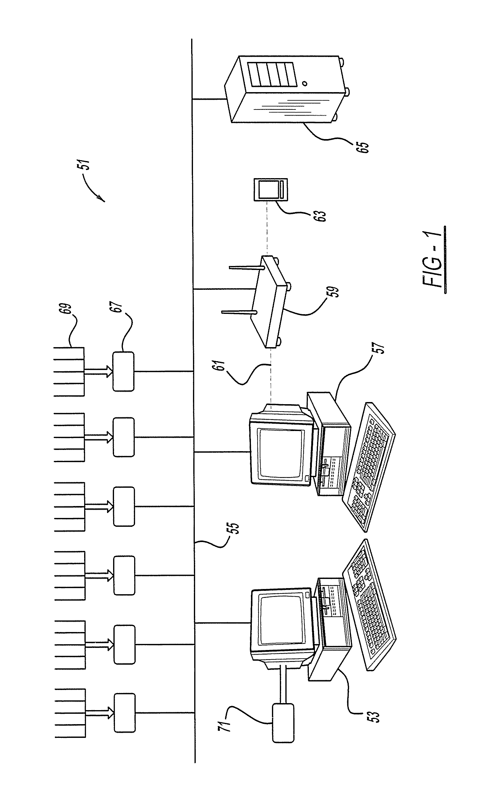
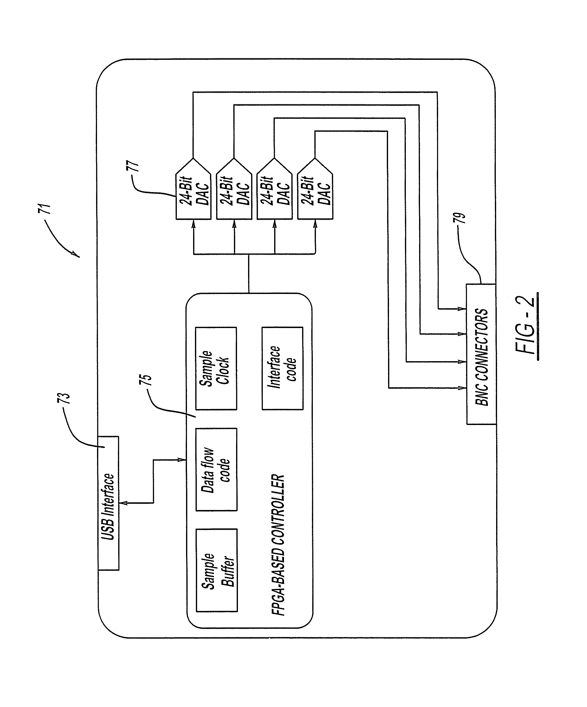
[0006]The present invention is advantageous over traditional devices since the present invention allows for essentially instantaneous, real-time data analysis by a centralized computer of the sensed machine operating conditions. This will save significant labor time and expense while also greatly improving the accuracy and timeliness of machine monitoring and maintenance. Certain aspects of the present system also advantageously employ evolutionary learning calculations to improve sensed data analysis and more accurate identification of machine problems. Furthermore, certain aspects of the present system allow for significantly reduced hardware costs by employing a switch matrix and multiplexer computer-to-sensor connection, which inexpensively proves at least 50, and more preferably 64, communication channels. Various aspects of the present system advantageously interface with a hand-held data collector, on-line databases and / or off-line databases, using hard-wired or wireless communications. The present system is ideally suited for use in cement manufacturing machinery, such as cement making kilns, crushers, conveyors, fans and the like. Additional advantages and features of the present invention will become apparent from the following description and appended claims, taken in conjunction with the accompanying drawings.BRIEF DESCRIPTION OF THE DRAWINGS

Problems solved by technology

This physical walk by monitoring is very time consuming and costly, and does not allow for easily managed and timely analysis of the sensed machine data.
These proposed systems, however are very crude and do very little, if any, automatic calculation and analysis of the monitored information.
This will save significant labor time and expense while also greatly improving the accuracy and timeliness of machine monitoring and maintenance.

Method used


Image

  • System for monitoring plant equipment
  • System for monitoring plant equipment
  • System for monitoring plant equipment

Examples


Embodiment Construction

[0031]The preferred embodiment of a system for monitoring plant equipment, more preferably cement manufacturing equipment and machinery, may be used to monitor the operating condition of many machines used to make cement, such as Portland cement. In general, the cement manufacturing process begins with extracting raw materials, such as limestone and clay, from a quarry, transporting the materials to crushing machines which reduce the size of the extracted rock, and conveying the crushed rock to grinders. Corrective materials such as iron, minerals and sand are mixed to the crushed material before it enters the raw mills for grinding, drying and pulverizing. The pulverized material is then transported to kiln machines where it is heated until the material forms clinker, which is subsequently cooled by fans. Next, the clinker is transported to storage silos and later sent to clinker grinding mills where it is mixed with gypsum and other materials, whereafter it is transported to stora...


PUM

PropertyMeasurementUnit
Vibrational spectrumaaaaaaaaaa

Abstract

A system for monitoring plant equipment is provided. Another aspect provides an automated analysis system wherein software instructions operably compare sensor data to predefined valves and determine mechanical problems in multiple machines. In another aspect, a cement manufacturing system includes sensors for sensing movement conditions of cement making machines. A further aspect provides a central computer connected to vibration sensors associated with cement making machines, where software instructions perform real-time comparisons and machine performance determinations, based at least in part on sensed signals.

Description

BACKGROUND AND SUMMARY[0001]This disclosure relates generally to manufacturing equipment and more particularly to a system for monitoring manufacturing plant machinery.[0002]Various diagnostic devices are known which monitor or determine a fault in general purpose machinery. Examples of this can be found in the following U.S. Pat. No. 7,010,445 entitled “Automated Fault Diagnosis Device and Method” which issued to Battenberg et al. on Mar. 7, 2006; U.S. Pat. No. 6,549,869 entitled “Expert Analysis Modules for Machine Testing” which issued to Piety et al. on Apr. 15, 2003; U.S. Pat. No. 6,839,660 entitled “On-Line Rotating Equipment Monitoring Device” which issued to Eryurek on Jan. 4, 2005; and U.S. Pat. No. 7,539,549 entitled “Motorized System Integrated Control and Diagnostics Using Vibration, Pressure, Temperature, Speed, and / or Current Analysis” which issued to Discenzo et al. on May 26, 2009. All of these patents are incorporated by reference herein. These conventional devices ...

Claims


Application Information

Patent Timeline
IPC IPC(8): G06F17/00G06F3/048G05B21/02G06N3/12
CPCF27B7/42G01N19/08G05B23/0235
Inventor LOUTFI, MOHEB Y.
Owner HOLCIM US
Learn More