Eureka AIR delivers breakthrough ideas for toughest innovation challenges, trusted by R&D personnel around the world.

Driving method for solenoid valve, solenoid valve driving apparatus, and combustion apparatus including same

Active Publication Date: 2011-07-28
NORITZ CORP
View PDF21 Cites 14 Cited by
  • Summary
  • Abstract
  • Description
  • Claims
  • Application Information

AI Technical Summary

Benefits of technology

[0010]An object of the present invention is to provide a driving method for a solenoid valve, a solenoid valve driving apparatus, and a combustion apparatus including the solenoid valve driving apparatus with which the problems described above can be appropriately prevented or suppressed.
[0013]Preferably, the driving method for a solenoid valve according to the present invention further includes a step of supplying the power to the solenoid of the solenoid valve by applying the direct current voltage to the solenoid intermittently during a valve open state maintaining period occurring after the solenoid valve has been set in the open state, wherein a valve reopening period in which the power supplied to the solenoid is increased by temporarily increasing the duty ratio of the voltage applied to the solenoid at a predetermined timing is provided during the valve open state maintaining period so that when the solenoid valve enters the closed state, the solenoid valve can be caused to perform the valve opening operation again.

Problems solved by technology

With the conventional technique described above, however, the following problems may occur.
During the valve opening operation of the solenoid valve, a voltage is simply applied to the solenoid at a duty ratio of 100%, and therefore, although the solenoid can be supplied with a large amount of power, a comparatively loud noise may be generated as the valve opens.
This noise is generated when a valve body of the solenoid valve and a plunger that supports the valve body are moved sharply by a large electromagnetic force from the solenoid such that a part of the plunger collides with a casing of the solenoid valve, for example.
However, when this means is employed alone, it may be difficult to execute the valve opening operation appropriately.
More specifically, for example, when a voltage of a direct current power supply connected to the solenoid valve becomes lower than a normal voltage for any reason, the power required for the valve opening operation may not be supplied to the solenoid valve, making it difficult to execute the valve opening operation appropriately.
Hence, it may also be difficult to execute the valve opening operation when a combustion operation is resumed in the combustion apparatus after stopping the combustion apparatus following an extended combustion operation.
Hence, when a momentary power failure (for example, a power failure that is too short for an operation-controlling microcomputer to be reset) occurs such that the solenoid valve enters a closed state, the amount of power supplied to the solenoid following resumption of the power supply is small, and it may therefore be impossible to return the solenoid valve to the open state appropriately.
The solenoid valve may be switched from the open state to the closed state unintentionally due to large pressure variation in a pipe passage to which the solenoid valve is attached, but with the conventional technique described above, it may likewise be impossible to return the solenoid valve to the open state in such a case.
As a result, the solenoid valve remains in the closed state when it should be in the open state, and this situation is undesirable.

Method used


Image

  • Driving method for solenoid valve, solenoid valve driving apparatus, and combustion apparatus including same
  • Driving method for solenoid valve, solenoid valve driving apparatus, and combustion apparatus including same
  • Driving method for solenoid valve, solenoid valve driving apparatus, and combustion apparatus including same

Examples


Embodiment Construction

[0032]A specific preferred embodiment of the present invention will be described below with reference to the drawings.

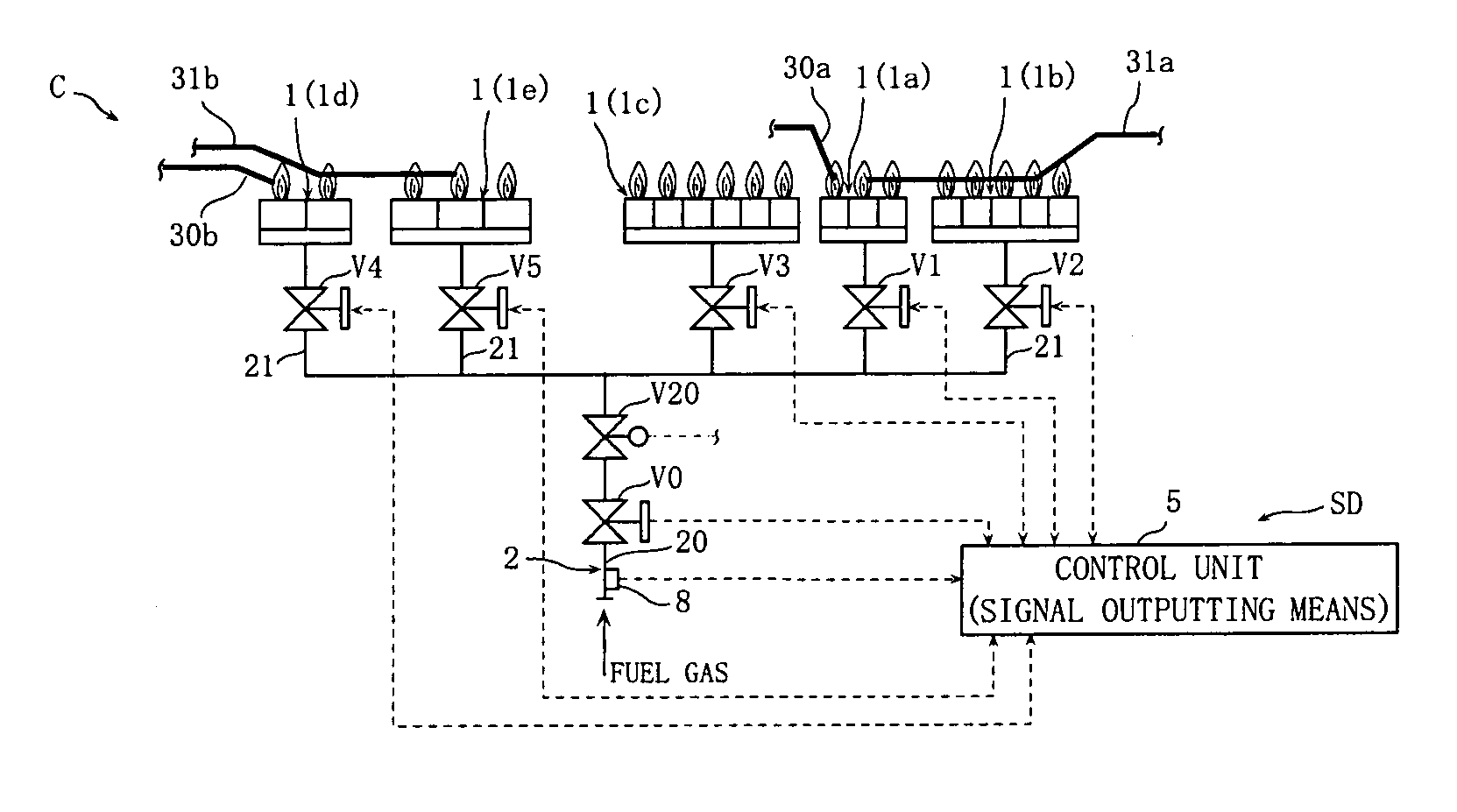
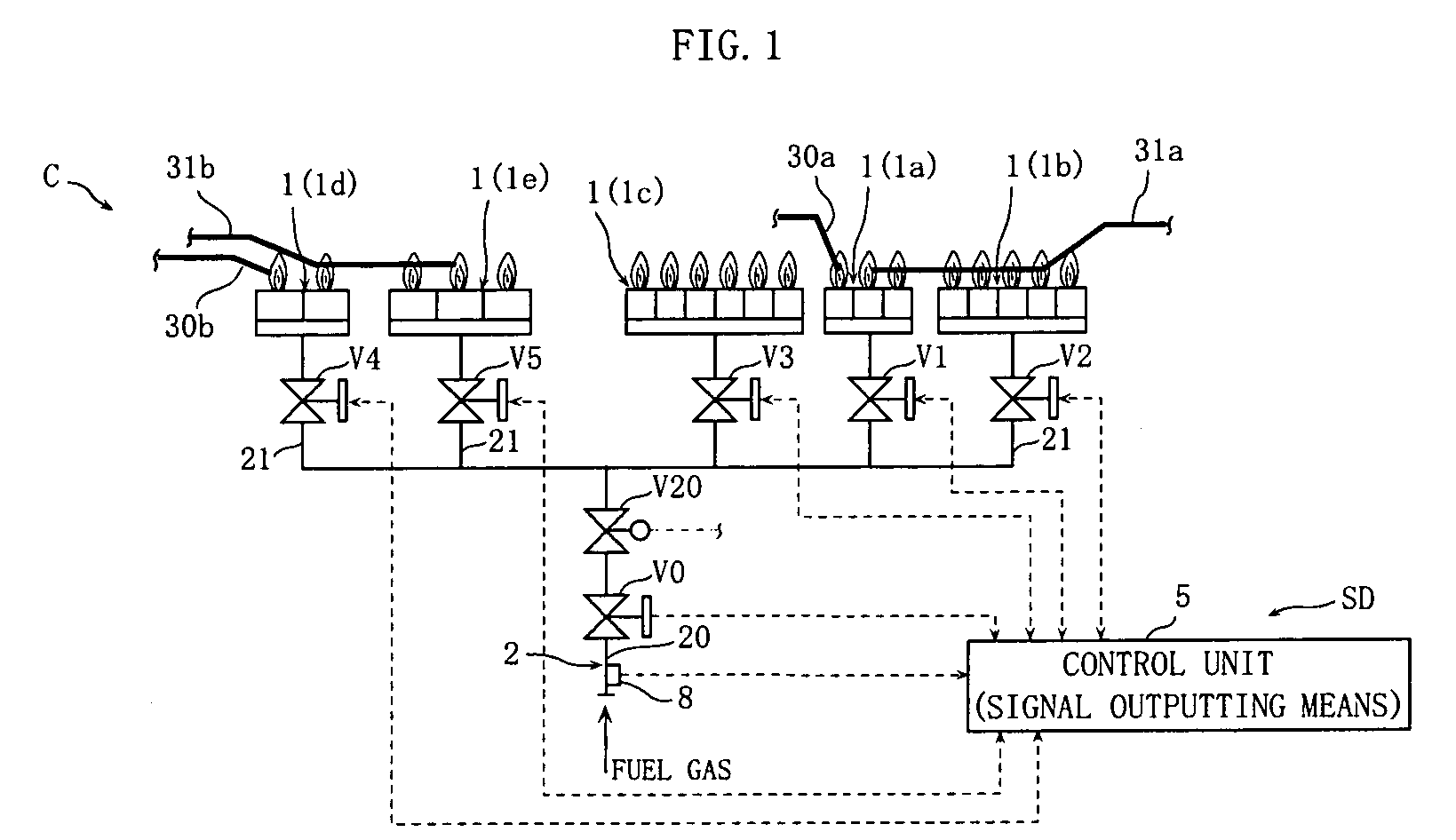
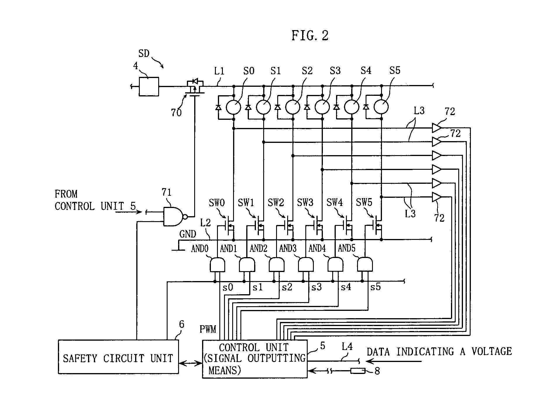
[0033]FIGS. 1 and 2 show an example of a combustion apparatus including a solenoid valve driving apparatus to which the present invention is applied. As shown in FIG. 1, a combustion apparatus C according to this embodiment includes a plurality of gas burners 1 (1a to 1e), a fuel gas supply passage 2, a plurality of solenoid valves V0 to V5, a motorized valve V20, a pressure sensor 8, and a solenoid valve driving apparatus SD. The solenoid valve driving apparatus SD includes a control unit 5.

[0034]The combustion apparatus C is provided in a water heating apparatus (not shown) that supplies hot water for general use and hot water for bathing, for example, and is used to supply a fuel gas to a water-heating heat exchanger (not shown) of the water heating apparatus. Note, however, that the combustion apparatus according to the present invention is not limited to use in ...


PUM


Abstract

A solenoid valve driving apparatus includes switching means for ON / OFF-controlling application of a direct current voltage to a solenoid of a solenoid valve, and signal outputting means. A first period and a consecutive second period are set as a valve opening operation period of the solenoid valve. When the signal outputting means outputs the PWM signal to the switching means, a duty ratio of the output signal is set to be higher in the second period than in the first period so that a power supplied to the solenoid is larger in the second period than in the first period. As a result, a valve opening operation is performed in the solenoid valve reliably, and loud noise generation during the valve opening operation is suppressed.

Description

BACKGROUND OF THE INVENTION[0001]1. Field of the Invention[0002]The present invention relates to a method for driving a solenoid valve serving as a fluid control device favorably, a solenoid valve driving apparatus, and a combustion apparatus including the solenoid valve driving apparatus.[0003]2. Description of the Related Art[0004]A solenoid valve is used to switch a fuel supply in a combustion apparatus ON and OFF, for example. Japanese Patent Application Publication No. S58-65384 describes an example of an apparatus for driving this type of solenoid valve.[0005]The apparatus described in this publication drives a solenoid valve using a PWM (Pulse Width Modulation) system, includes a switching element for switching application of a direct current voltage to a solenoid of the solenoid valve ON and OFF, and uses a PWM signal as a control signal for operating the switching element. When the solenoid valve is caused to perform a valve opening operation, a signal having a duty ratio o...

Claims


Application Information

Patent Timeline
IPC IPC(8): F23K5/14H01H47/32
CPCF23K5/147F23N1/002F23N5/203H01H47/325F23N2035/16F23N2037/02F23N2035/14F23N2235/14F23N2235/16F23N2237/02
Inventor KONISHI, DAISUKEOHTA, AKIRAKITANO, YOSHIHISANAKANO, TOMOYAATOBE, YOSHIFUMIINOUE, HARUKIKIMURA, YOSHITAKAIKEDA, RYOKISHIMOTO, TOMOKIIKEUCHI, YASUHIDEIKEUCHI, TOMOKO
Owner NORITZ CORP
Why Eureka
Eureka Blog
Learn More