High-power direct current engine comprising a collector and carbon brushes for a racing car serving as prototype
a technology of dc motor and collector, which is applied in the direction of rotary current collector, dynamo-electric machines, electrical apparatus, etc., can solve the problems of reducing affecting the quality of the current transmission, and affecting the operation of the commutator, so as to reduce the electrical resistance of the power supply to the commutator and reduce the power of the motor
- Summary
- Abstract
- Description
- Claims
- Application Information
AI Technical Summary
Benefits of technology
Problems solved by technology
Method used
Image
Examples
first embodiment
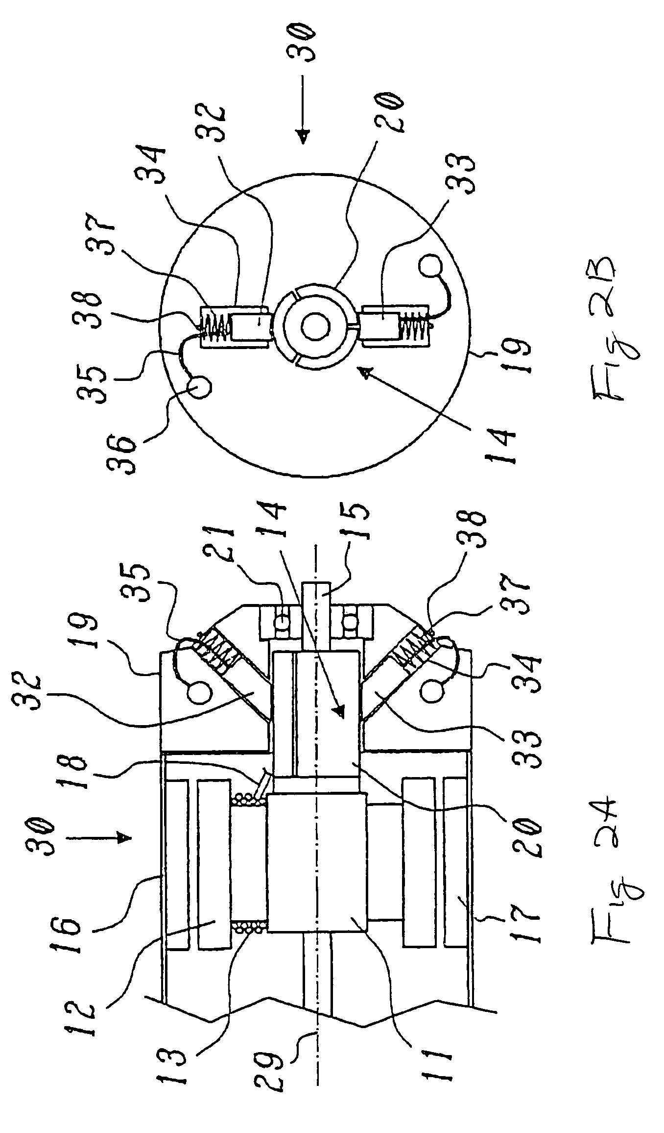
[0050]FIGS. 2A and 2B show a DC motor according to the invention, with FIG. 2A showing a longitudinal section through the motor and FIG. 2B showing a plan view in the direction of the axis. The same parts are in this case provided with the same reference symbols as in FIGS. 1A and 1B. FIG. 3 shows an enlarged detailed view of one of the brushes from FIG. 2A.
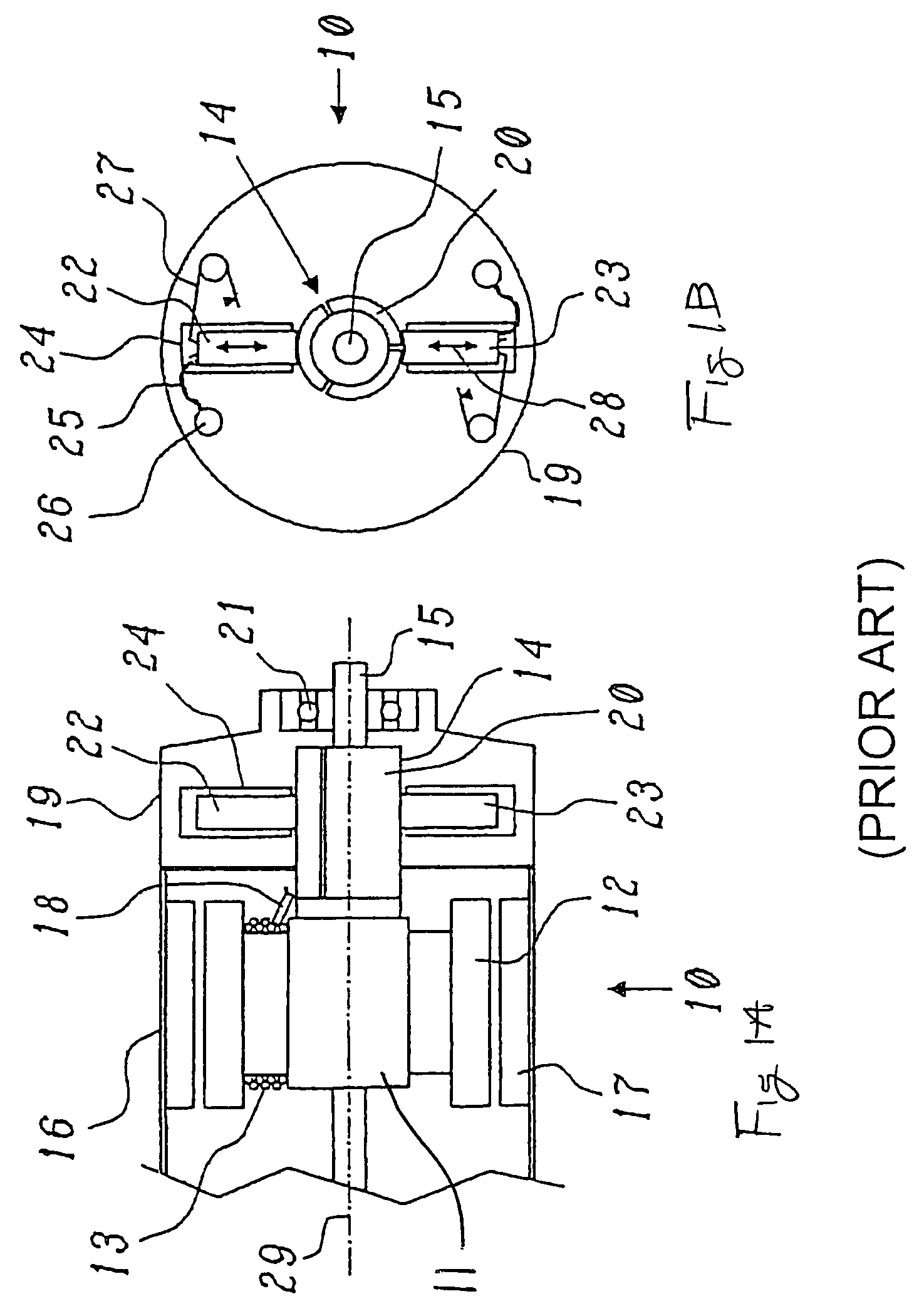
[0051]The DC motor illustrated in FIGS. 2A and 2B differs from the known motor shown in FIGS. 1A and 1B by the arrangement of the brushes 32, 33 relative to the (unchanged) commutator 14. The brushes 32, 33 are oriented with their associated brush boxes 34 obliquely outwards, so that their movement direction 39 (double-headed arrow in FIG. 3), which is predetermined by the brush boxes 34 and is the same as the direction of the force vector C in the force parallelogram shown in FIG. 3, includes an angle α (alpha) with the radial direction with respect to the axis 29, which is at the same time the direction of the normal to the com...
second embodiment
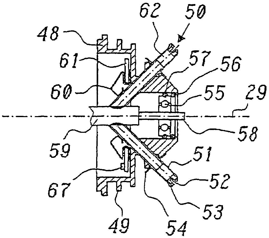
[0054]FIGS. 4A and 4B show a DC motor 40 according to the invention, with FIG. 4A showing a longitudinal section through the motor and FIG. 4B showing a plan view in the axial direction. The same parts are in this case provided with the same reference symbols as in FIGS. 1A and 1B. FIG. 5 shows an enlarged detailed view of one of the brushes from FIG. 4B.
[0055]As can be seen from FIG. 4B, the brush boxes 44 for the brushes 42, 43 no longer lie on a common plane which passes through the axis 29, but on a common plane which is at right angles to the axis 29 (see FIG. 4A). The oblique position of the movement direction 41 (FIG. 5) relative to the radial direction (the dashed line in the force parallelogram in FIG. 5) is in this case achieved by the two brushes 42, 43 being arranged laterally offset parallel in the opposite direction from the position shown in FIG. 1B. This also results in a tilt angle α, which leads to the radial force A being resolved into two mutually perpendicular f...
PUM
 Abstract
Description
Claims
Application Information
 - R&D
- Intellectual Property
- Life Sciences
- Materials
- Tech Scout
- Unparalleled Data Quality
- Higher Quality Content
- 60% Fewer Hallucinations
Browse by: Latest US Patents, China's latest patents, Technical Efficacy Thesaurus, Application Domain, Technology Topic, Popular Technical Reports.
© 2025 PatSnap. All rights reserved.Legal|Privacy policy|Modern Slavery Act Transparency Statement|Sitemap|About US| Contact US: help@patsnap.com


