
Ink jet recording system and recording method

Active Publication Date: 2011-07-28
SEIKO EPSON CORP
View PDF12 Cites 25 Cited by
  • Summary
  • Abstract
  • Description
  • Claims
  • Application Information

AI Technical Summary

Benefits of technology

[0008]According to the first aspect, the ink jet recording system has the drying portion as the first fixing portion that evaporates 40 to 70% by weight of the ink adhering to the target recording medium and the irradiation device that irradiates the target recording medium with ultraviolet ray or electron beam as the second fixing portion provided at the downstream side with respect to the drying portion of the feeding direction of the target recording medium. Therefore, by evaporating 40% by weight or more of the ink adhering to the target recording medium In the drying portion also in the case of printing at high speed, the occurrence of line width unevenness (beading) in printing of ruled lines to the target recording medium, color unevenness or mixture of different colors (color bleed) in solid printing, or the like can be prevented. In addition, by not evaporating more than 70% by weight of the ink adhering to the target recording medium in the drying portion, the adhesion dot diameter of ink droplets can be secured on the target recording medium and the occurrence of discontinuous lines in the case of printing of ruled lines or unevenness in the case of solid printing can be prevented. Moreover, a reduction in the scratch resistance due to an increase in the thickness of the adhesion dot of ink droplets can also be prevented.
[0010]The second aspect can be preferably adopted as the ink of the first aspect of the invention and can further increase the effects of the ink jet recording system according to the first aspect of the invention.
[0012]The third aspect can be preferably adopted as the ink of the first or second aspect of the invention and can further increase the effects of the ink jet recording system according to the first aspect of the invention.
[0014]The fourth aspect can be preferably adopted as the ink of the third aspect of the invention and can further increase the effects of the ink jet recording system according to the first aspect of the invention.

Problems solved by technology

However, when ink jet recording is performed at high speed on a target recording medium having remarkably low ink absorbability, such as cast paper or a plastic film for offset printing, high-quality image printing at high speed cannot be performed by a device using a former drying measure.
This is because there has been problems, for example, in that line width unevenness (beading) in printing of ruled lines, color unevenness or mixture of different colors (color bleed) in solid printing, or the like occurs.

Method used


Image

  • Ink jet recording system and recording method
  • Ink jet recording system and recording method
  • Ink jet recording system and recording method

Examples


Embodiment Construction

[0023]Hereinafter, the embodiments of the invention will be described with reference to the drawings.

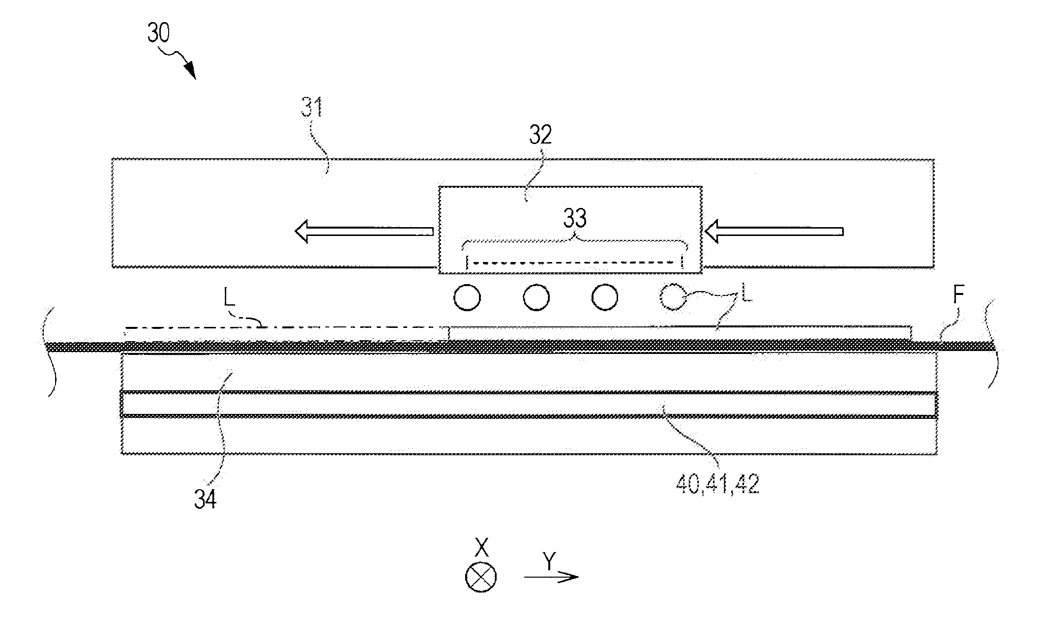
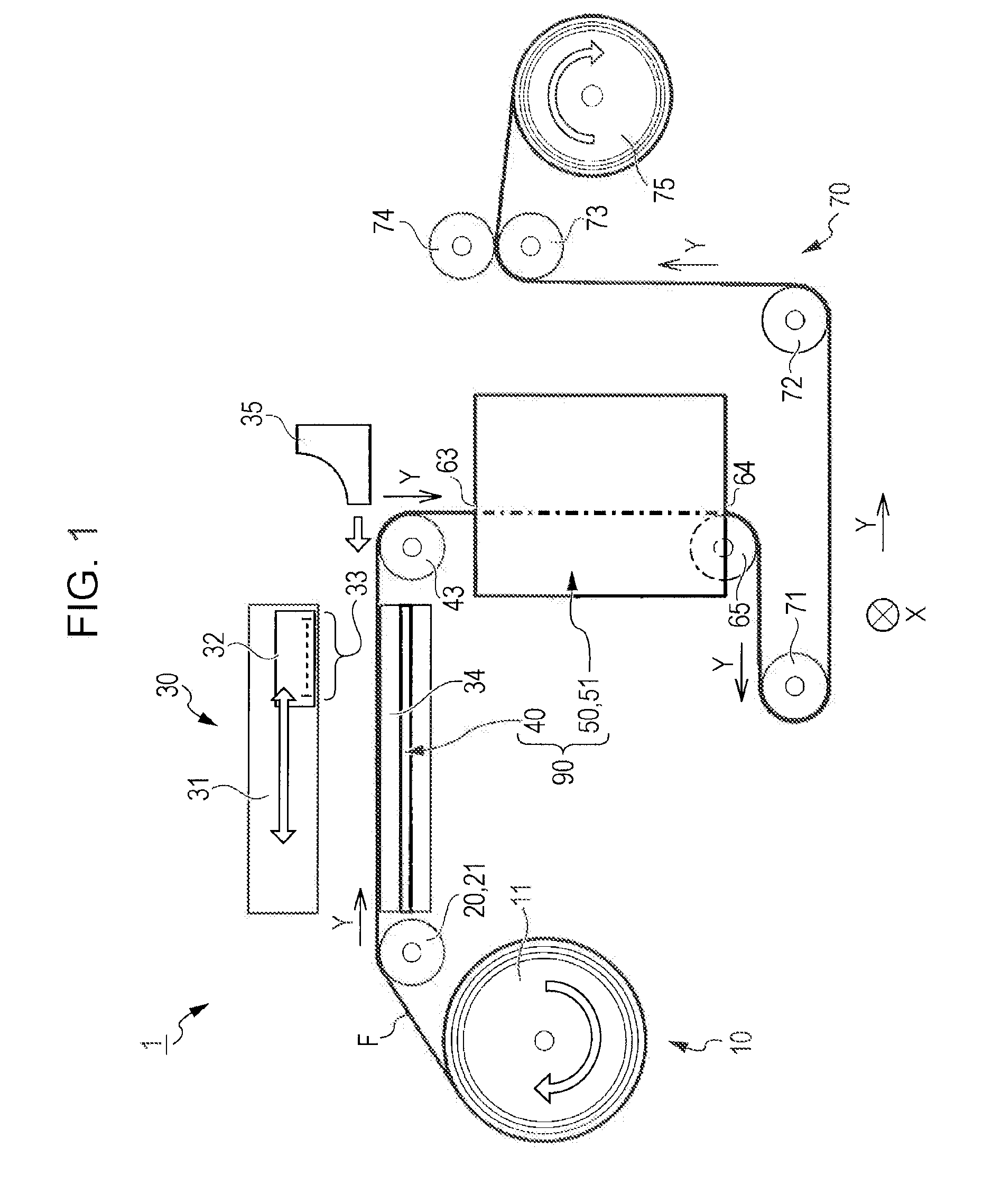
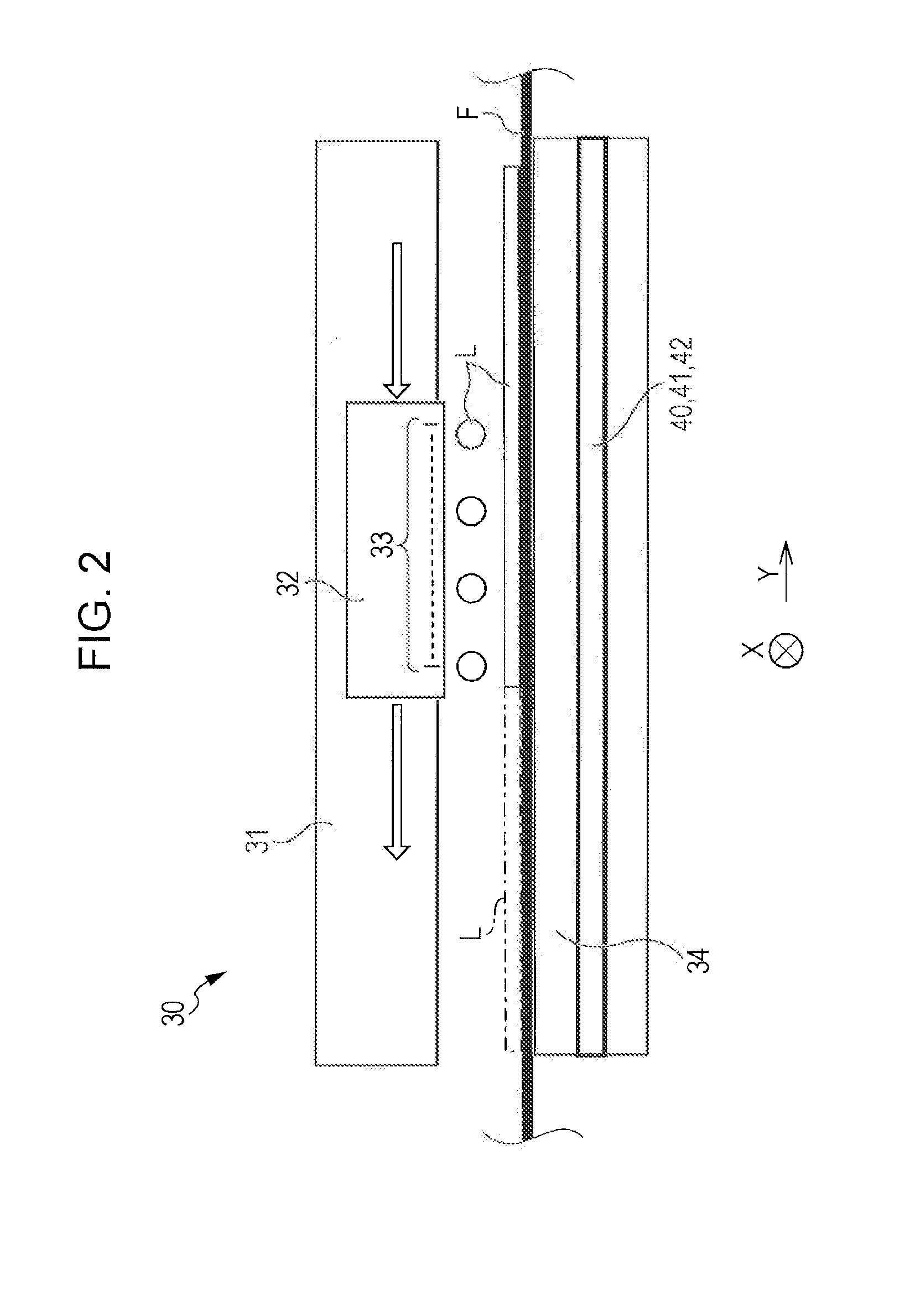
[0024]FIG. 1 illustrates a side view illustrating the outline of an entire ink jet recording device 1 according to this embodiment.

[0025]As illustrated in FIG. 1, the ink jet recording device 1 has a feeding portion 10 of a target recording medium, a transporting portion 20, a recording portion 30, a fixing portion 90, and an ejecting portion 70.

[0026]Among the above, the fixing portion 90 has a drying portion 40 as a first fixing portion and a second fixing portion 50 described later.

[0027]The feeding portion 10 is provided in such a manner as to feed a target roll-shaped recording medium F as an example of the target recording medium to the transporting portion 20.

[0028]Specifically, the feeding portion 10 has a roll medium holder 11 and the roll medium holder 11 holds a target roll-shaped recording medium F. It is structured that, by rotating the target roll-shaped recording mediu...


PUM


Abstract

An ink jet recording system, contains a recording head that ejects ink to the surface of a target non-ink-absorbing or low ink-absorbing recording medium; a medium support portion that faces the recording head and supports the target recording medium from the back surface; a drying portion as a first fixing portion that evaporates a liquid ingredient of the ink that is ejected to the target recording medium from the recording head and adheres thereto; and a second fixing portion at the downstream side with respect to the drying portion of a feeding direction of the target recording medium, the second fixing portion is an irradiation device that irradiates the target recording medium with ultraviolet ray or electron beam, and the evaporation amount of the liquid ingredient in the drying portion is 40 to 70% by weight of the ink adhering to the target recording medium.

Description

BACKGROUND[0001]1. Technical Field[0002]The present invention relates to an ink jet recording system and a recording method that perform high-quality image recording at high speed on a target non-ink-absorbing or low ink-absorbing recording medium.[0003]2. Related Art[0004]Heretofore, as described in Japanese Unexamined Patent Application Publication No. 6-126952, an ink jet recording device has been proposed to have a preheating lamp as an ink drying measure and an air blowing measure thereon. Among the above, the preheating lamp is provided in such a manner as to heat a driving roller and the driving roller is constituted so that the target recording medium is heated before passing a printing zone. In contrast, the air blowing measure is constituted in such a manner as to supply a strong wind to the target recording medium immediately after printing in a printing zone and heat the same.[0005]However, when ink jet recording is performed at high speed on a target recording medium ha...

Claims


Application Information

Patent Timeline
IPC IPC(8): B41J2/01
CPCB41J11/002B41J11/00214B41J11/00244
Inventor TAKEMOTO, KIYOHIKO
Owner SEIKO EPSON CORP
Learn More