
Methods and apparatus for active patient warming

a patient and active technology, applied in the field of active patient warming devices, can solve the problems of poor heat transfer, noisy equipment, and large volume of equipment to control bladder-based blankets, and achieve the effects of limiting overheating, facilitating accurate calibration of heater cells, and minimizing hot spots across patient warming devices

Inactive Publication Date: 2011-07-14
VYAIRE MEDICAL CONSUMABLES LLC
View PDF21 Cites 38 Cited by
  • Summary
  • Abstract
  • Description
  • Claims
  • Application Information

AI Technical Summary

Benefits of technology

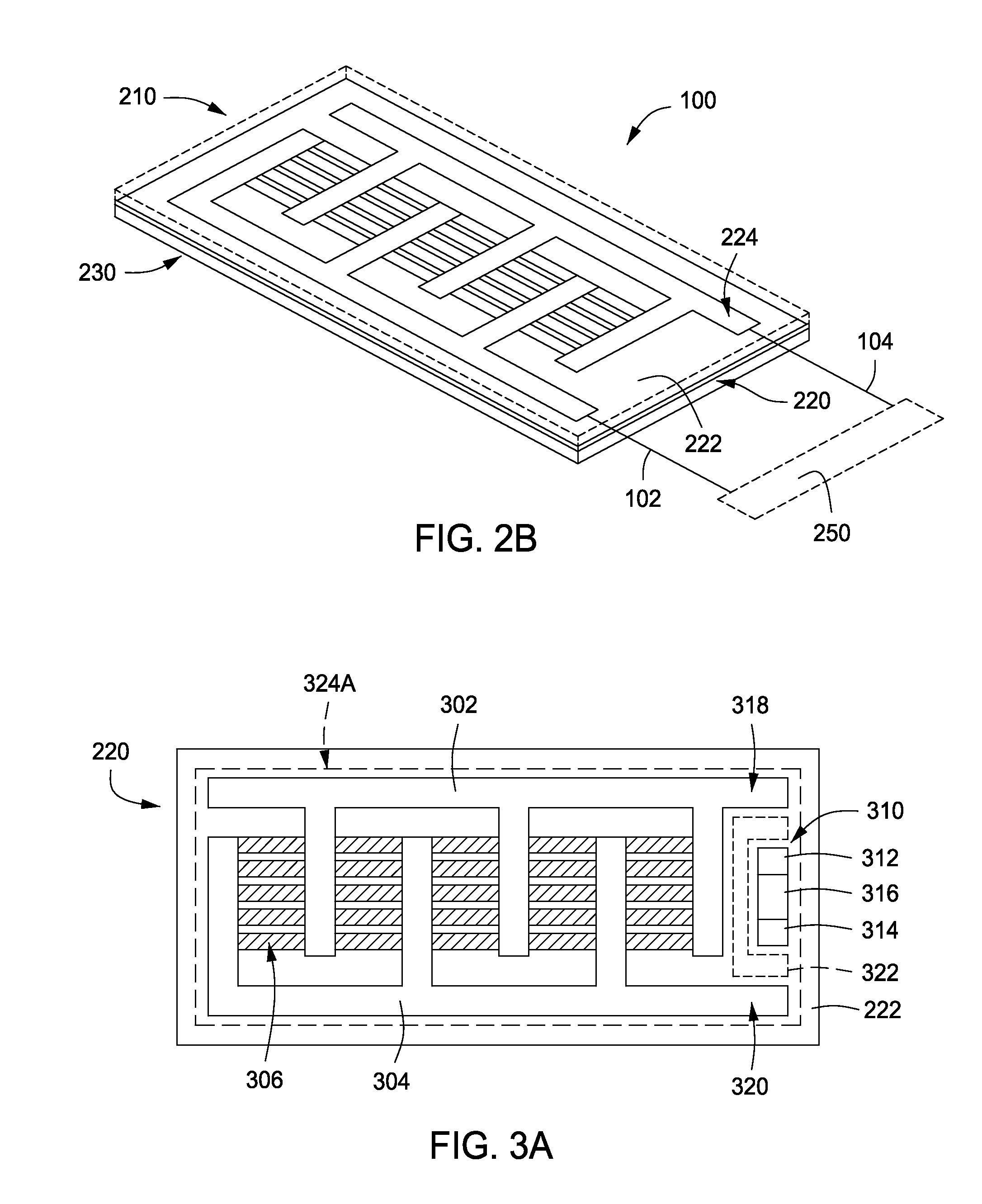
Methods and apparatus for warming a patient are disclosed herein. In some embodiments, a patient warming device may include a heater layer comprising a plurality of heater cells disposed on a flexible substrate; and a thermal conduction layer disposed on a patient side of the heater layer to transfer heat generated by the heater layer to a patient. The heater cells may comprise an electrical circuit to generate heat by Joule heating. In some embodiments, the resistive heaters may include a positive temperature coefficient (PTC) or a negative temperature coefficient (NTC) material having a switching temperature adapted to limit overheating as would be perceived by a patient. The use of miniature PTC resistive heaters or miniature NTC resistive heaters minimizes hot spots across the patient warming device because each heater can self-regulate independently. In some embodiments, a temperature sensor may be provided to provide closed-loop control of the power delivered to the heater cells and, therefore, the heat that is conveyed to the patient. In some embodiments, the electrical resistance across a heater cell may be measured during operation, thereby allowing the heater cell to be used as the temperature sensor. In some embodiments, a second temperature sensor may be placed in thermal contact with the heater cell, thereby facilitating accurate calibration of the heater cell as the temperature sensor. The patient warming device is flexible to facilitate conforming the patient warming device to a patient during use.

Problems solved by technology

Such blankets are typically large, and heat transfer can be poor since air is a poor carrier and conductor of heat.
The equipment to control such bladder-based blankets is often large and bulky.
In addition, in the heated air versions, the equipment is noisy.
Other devices with resistive heaters have tended to have insulator layers, and have a propensity to form hot spots due to uneven generation of heat between or uneven conductance of heat away from portions of the resistive heater.

Method used


Image

  • Methods and apparatus for active patient warming
  • Methods and apparatus for active patient warming
  • Methods and apparatus for active patient warming

Examples


Embodiment Construction

Embodiments of the present invention include methods and apparatus for warming a patient. The inventive patient warming device generally provides local temperature control with few or no hotspots to enhance patient safety and to facilitate efficiently getting heat to the patient. The inventive patient warming device may be reusable or disposable. The inventive patient warming device operates without air or water flow, which facilitates simpler and quieter operation, with no air and / or water flow control mechanisms, and no fluid flows that can create contamination risk and / or maintenance issues.

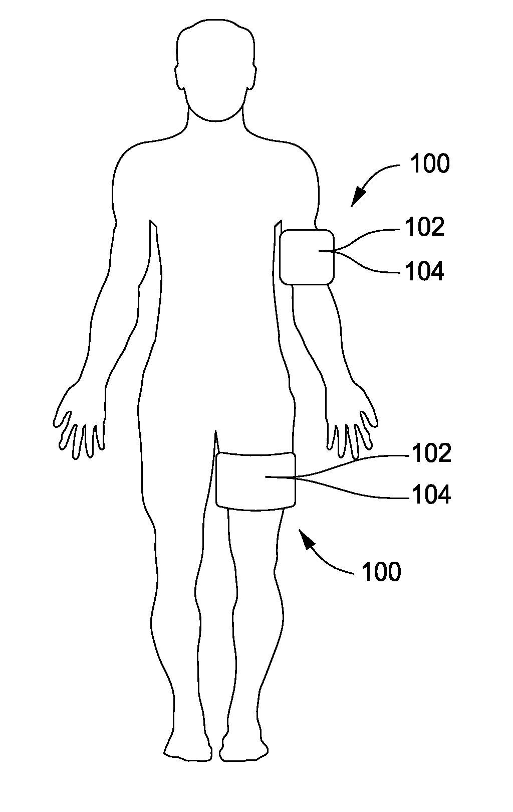
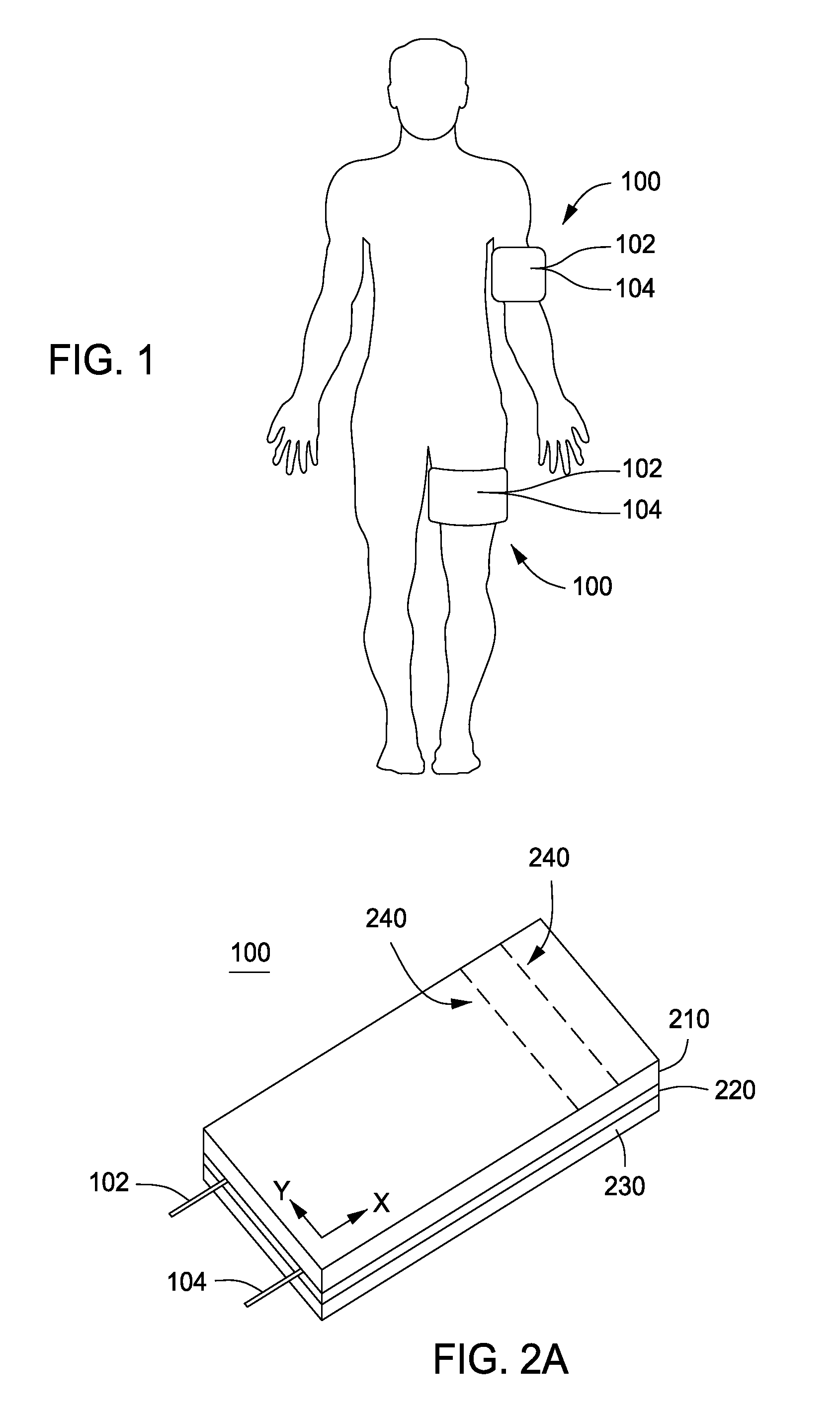
FIG. 1 illustratively depicts the application of two patient warming devices 100 to a patient. The patient warming devices 100 may be applied to the skin of the patient in any convenient location, for example, on the upper arm or thigh. The patient warming device 100 is a flexible device that can be wrapped around a patient, or a portion of a patient, such as about an arm or thigh as shown in ...


PUM


Abstract

Methods and apparatus for warming a patient are disclosed herein. In some embodiments, a patient warming device may include a heater layer comprising a plurality of heater cells disposed on a flexible substrate; and a thermal conduction layer disposed on a patient side of the heater layer to transfer heat generated by the heater layer to a patient. The heater cells may comprise an electrical circuit to generate heat by Joule heating. The patient warming device is flexible to facilitate conforming the patient warming device to a patient during use.

Description

FIELDEmbodiments of the present invention generally relate to devices and methods for warming a patient.BACKGROUNDA body surface warmer is a device which helps maintain or increase a patient's temperature at or to a normothermic level by conducting heat into the body at the skin surface and utilizing the patient's circulatory system to distribute the heat to other portions of the body. Such devices can also be used in physical therapy or other areas requiring localized heating.One common form of body surface warmer is a device in which warm air is pumped into an air mattress type blanket. Such blankets are typically large, and heat transfer can be poor since air is a poor carrier and conductor of heat. In some devices, warm water is pumped into a chambered mattress-type blanket. Water is a superior heat conveyer, but the water chambers are typically packaged in an insulator layer. In use, the insulator layer and air gaps limit thermal conductance to the patient.Because there are lar...

Claims


Application Information

Patent Timeline
IPC IPC(8): A61F7/00
CPCA61F7/007A61F7/0097A61F7/02A61F2007/0001A61F2007/0071A61F2007/0295A61F2007/0086A61F2007/0095A61F2007/0268A61F2007/0269A61F2007/0279A61F2007/0074A61F2007/0029
Inventor CASSIDY, DAVID ELLSWORTHCARVALHO, BRUCE L.
Owner VYAIRE MEDICAL CONSUMABLES LLC
Learn More