Reactor and reaction plant
a technology of reacting plant and reactor, which is applied in the direction of temperatue control, process and machine control, instruments, etc., can solve the problems of high reaction yield and decrease in reaction by-products, and achieve the effect of suppressing side reactions, reducing diffusion length, and facilitating miscibility of fluid plurality
- Summary
- Abstract
- Description
- Claims
- Application Information
AI Technical Summary
Benefits of technology
Problems solved by technology
Method used
Image
Examples
embodiment 1
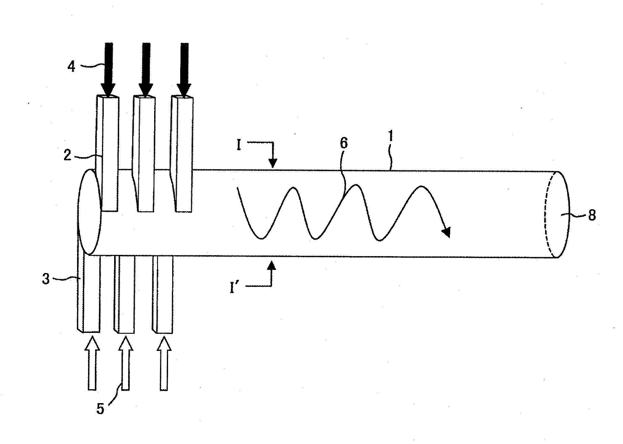
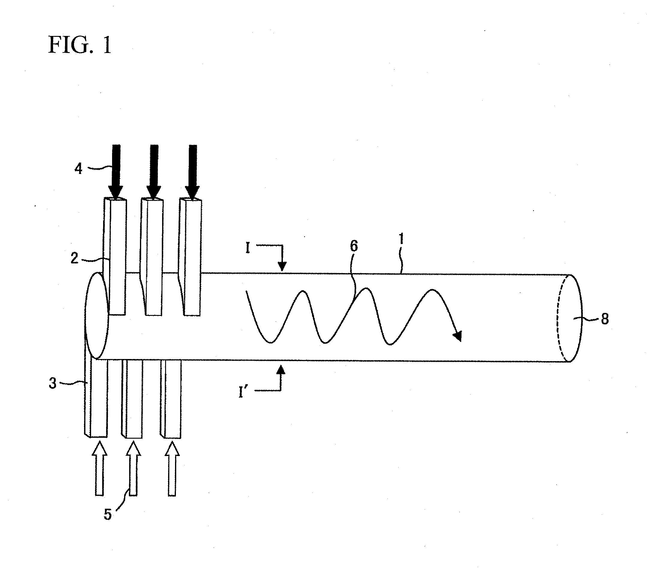
[0064]Embodiment 1 according to the present invention will be described with reference to FIGS. 1 to 9. FIG. 1 is a configuration view of a reactor according to the present embodiment.
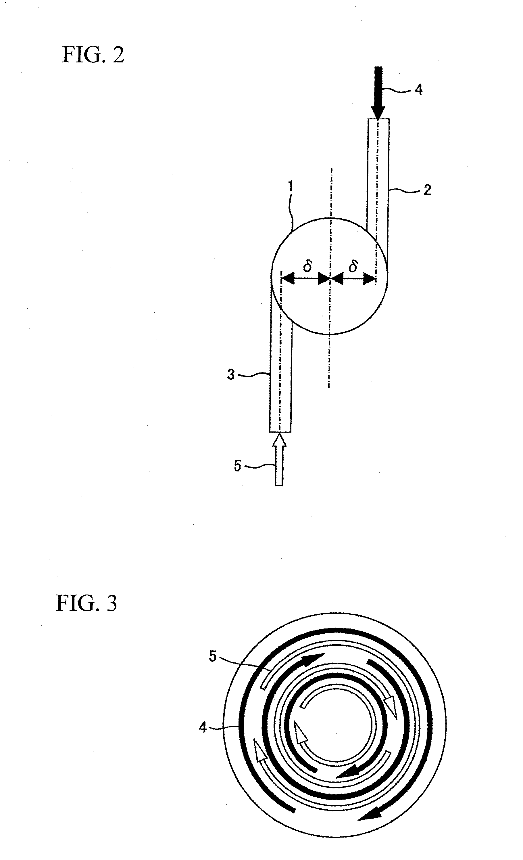
[0065]As shown in FIG. 1, an end of a cylindrically-shaped mixing channel 1 is sealingly closed, and on a side of the sealingly-closed end, there are provided an inlet passage 2 for introducing a fluid 4 containing a substance A into the mixing channel 1 and an inlet passage 3 for introducing a fluid 5 containing a substance B into the mixing channel 1. The inlet passages 2 and 3 are plurally provided in a spaced-apart manner in a flow direction of the mixing channel 1. As shown in FIG. 2, each of the inlet passages 2 and 3 is arranged at a position offset by a distance of 6 with respect to a central axis of the mixing channel 1. The inlet passages 2 and 3 are placed on an identical plane orthogonal to the central axis of the mixing channel 1, and are positioned in a direction opposite to each other. I...
embodiment 2
[0091]Embodiment 2 according to the present invention will be described with reference to FIGS. 10 and 11. FIG. 10 is a longitudinal sectional view illustrating the mixing channel according to the present embodiment. FIG. 11 is a perspective view illustrating a method for manufacturing the present embodiment.
[0092]The present embodiment is configured similarly to Embodiment 1. However, in the present embodiment, a structure 13 is mounted at the center of the channel of a part where the inlet passages 2 and 3 are placed, of the mixing channel 1. A cross-sectional area, of the structure 13, in a direction perpendicular to the central axis of the mixing channel 1 is shaped so as to decrease in the flow direction.
[0093]Such structure leads to a decrease in the cross-sectional area of the channel at an inlet passage part of the mixing channel 1, so that the width of the layer of the respective fluids 4 and 5 is lessened, and the diffusion length decreases, thereby improving the mixing pe...
embodiment 3
[0096]Embodiment 3 according to the present invention will be described with reference to FIG. 12. FIG. 12 is a perspective view illustrating a structure for controlling temperature in the mixing channel. The reactor 9 has a block structure, so that its heat transfer performance is likely to be lowered. An improvement in the reaction yield requires precise temperature control. Accordingly, in order to improve the heat transfer performance of the reactor having the block structure, a plurality of flow paths 15 for distributing a heat medium 16 are provided as illustrated in FIG. 12. The flow path 15 may be plurally provided along the mixing channel 1, or may be provided along the inlet passages 2 and 3.
[0097]In addition, although not illustrated in the figure, a plurality of fins may be provided in the reactor 9 in place of the flow paths 15.
[0098]As described above, according to the present embodiment, it is possible to perform the temperature control along the mixing channel 1, so ...
PUM
 Abstract
Description
Claims
Application Information
 - R&D
- Intellectual Property
- Life Sciences
- Materials
- Tech Scout
- Unparalleled Data Quality
- Higher Quality Content
- 60% Fewer Hallucinations
Browse by: Latest US Patents, China's latest patents, Technical Efficacy Thesaurus, Application Domain, Technology Topic, Popular Technical Reports.
© 2025 PatSnap. All rights reserved.Legal|Privacy policy|Modern Slavery Act Transparency Statement|Sitemap|About US| Contact US: help@patsnap.com


