Piezoelectric pump
- Summary
- Abstract
- Description
- Claims
- Application Information
AI Technical Summary
Benefits of technology
Problems solved by technology
Method used
Image

Examples
first preferred embodiment
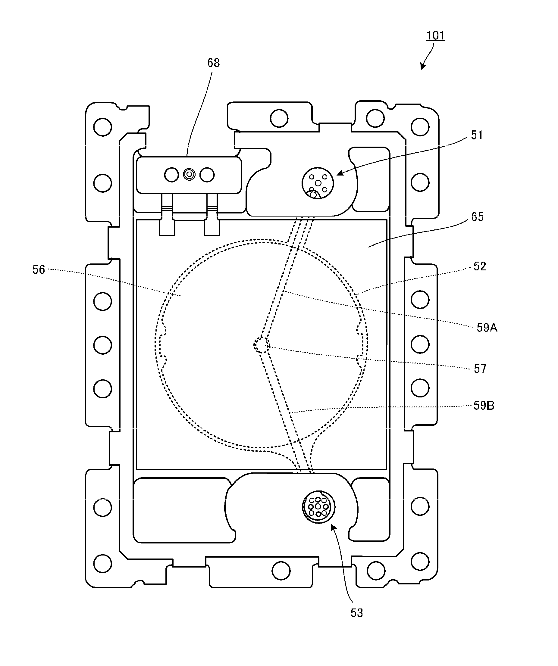
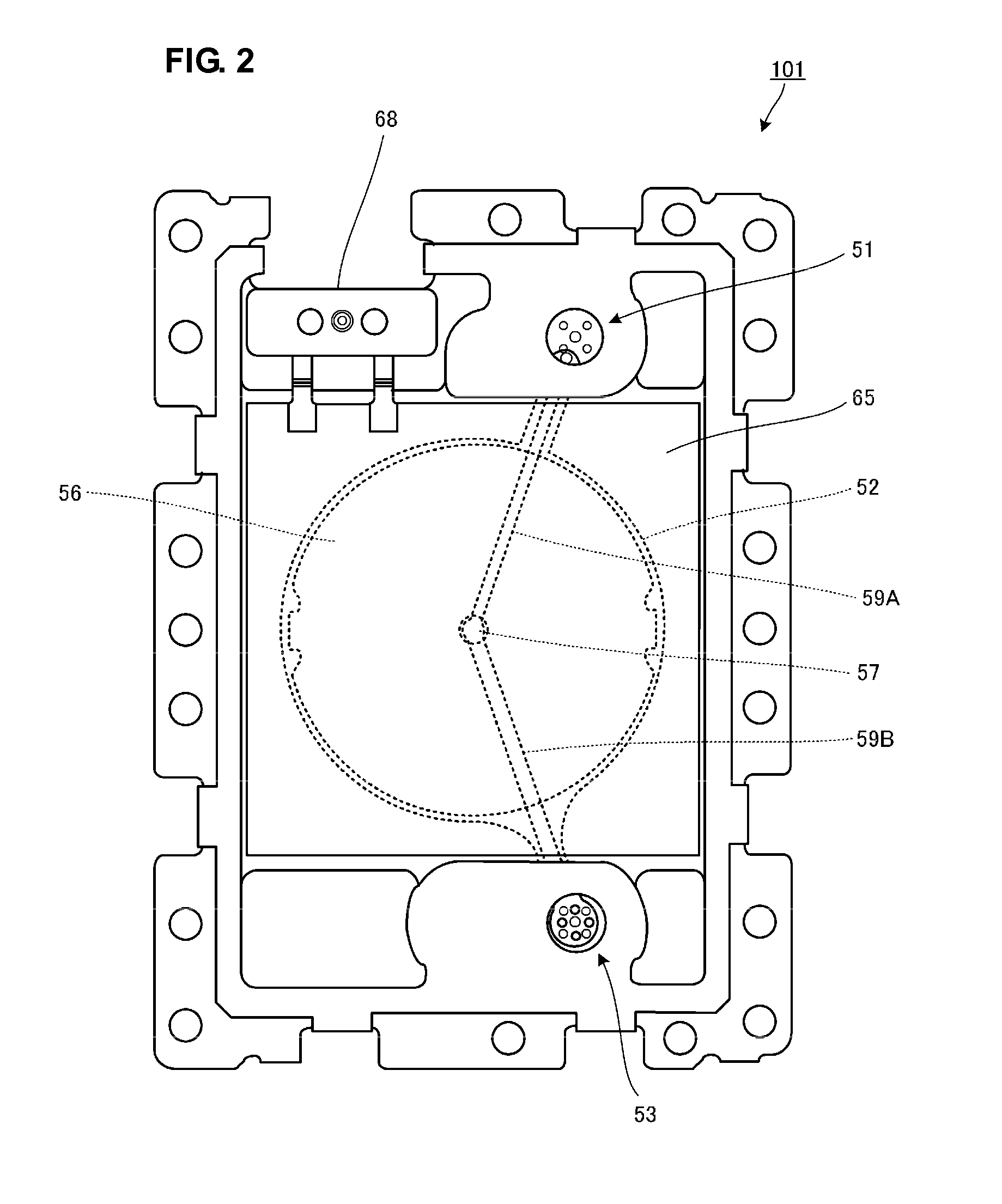
[0039]FIG. 2 is a plan view of a piezoelectric pump 101 according to a first preferred embodiment of the present invention. The piezoelectric pump 101 preferably includes a rectangular or substantially rectangular piezoelectric vibrator 65, a diaphragm that is deflected and deformed by the piezoelectric vibrator 65, a circular or substantially circular pump chamber including the diaphragm defining one side wall thereof, an inlet 51 through which liquid, gas, or a mixture thereof enters the pump chamber, an outlet 53 through which the fluid is discharged, and a liquid holding member 56 that provides a gap between the inner surface of the pump chamber and the liquid holding member 56 and holds the liquid using capillary effect or surface tension.
[0040]The inner surface of the pump chamber preferably includes flow passage grooves 59A and 59B in the inner surface thereof for the fluid. The liquid holding member 56 preferably includes an opening 57 in the approximate center thereof. The ...
second preferred embodiment
[0088]FIG. 7 is a cross-sectional view of a piezoelectric pump 102 according to a second preferred embodiment of the present invention. FIG. 7 corresponds to FIG. 4B of the first preferred embodiment. That is, FIG. 7 is a cross-sectional view of the piezoelectric pump 102 cut by a plane that passes through the center of the pump chamber 52 and that is substantially perpendicular to a direction in which the flow passage grooves 59 extend.
[0089]Unlike the piezoelectric pump 101 described in the first preferred embodiment, the piezoelectric pump 102 preferably includes two liquid holding members 56A and 56B inside the pump chamber 52. The remaining structure is substantially the same as that of the first preferred embodiment.
[0090]The thickness of the stacked liquid holding members 56A and 56B is preferably slightly less than the thickness of the pump chamber plate 63 that determines the height (the thickness) of the pump chamber 52. Accordingly, a gap is preferably provided between th...
third preferred embodiment
[0093]FIG. 8 is a cross-sectional view of a piezoelectric pump 103 according to a third preferred embodiment of the present invention. FIG. 8 corresponds to FIG. 4B of the first preferred embodiment. That is, FIG. 8 is a cross-sectional view of the piezoelectric pump 103 cut by a plane that passes through the center of the pump chamber 52 and that is substantially perpendicular to a direction in which the flow passage grooves 59 extend.
[0094]Unlike the piezoelectric pump 101 described in the first preferred embodiment, the piezoelectric pump 103 preferably includes the liquid holding member 56 and a liquid holding member 58 inside the pump chamber 52. The remaining structure is substantially the same as that of the first preferred embodiment.
[0095]The liquid holding member 56, which is one of two liquid holding members, is preferably made of the same material as that used for the liquid holding member 56 of the first preferred embodiment or that used for the liquid holding members 5...
PUM
 Abstract
Description
Claims
Application Information
 - R&D
- Intellectual Property
- Life Sciences
- Materials
- Tech Scout
- Unparalleled Data Quality
- Higher Quality Content
- 60% Fewer Hallucinations
Browse by: Latest US Patents, China's latest patents, Technical Efficacy Thesaurus, Application Domain, Technology Topic, Popular Technical Reports.
© 2025 PatSnap. All rights reserved.Legal|Privacy policy|Modern Slavery Act Transparency Statement|Sitemap|About US| Contact US: help@patsnap.com