Orifice plate and manufacturing method of the orifice plate
- Summary
- Abstract
- Description
- Claims
- Application Information
AI Technical Summary
Benefits of technology
Problems solved by technology
Method used
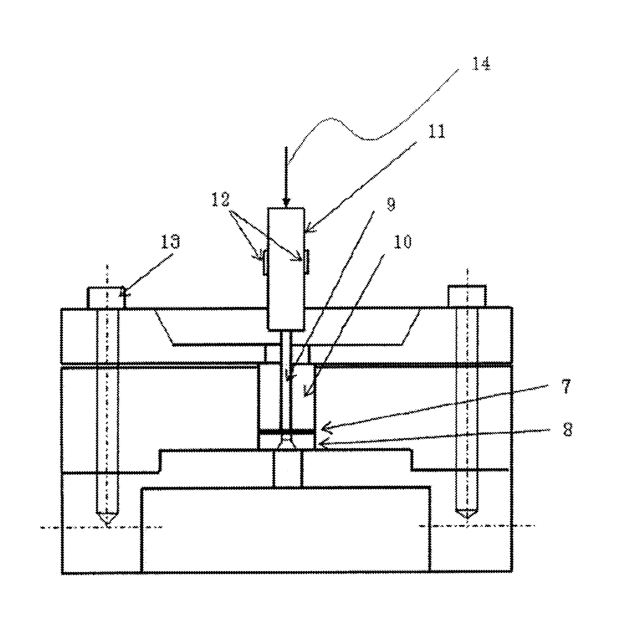
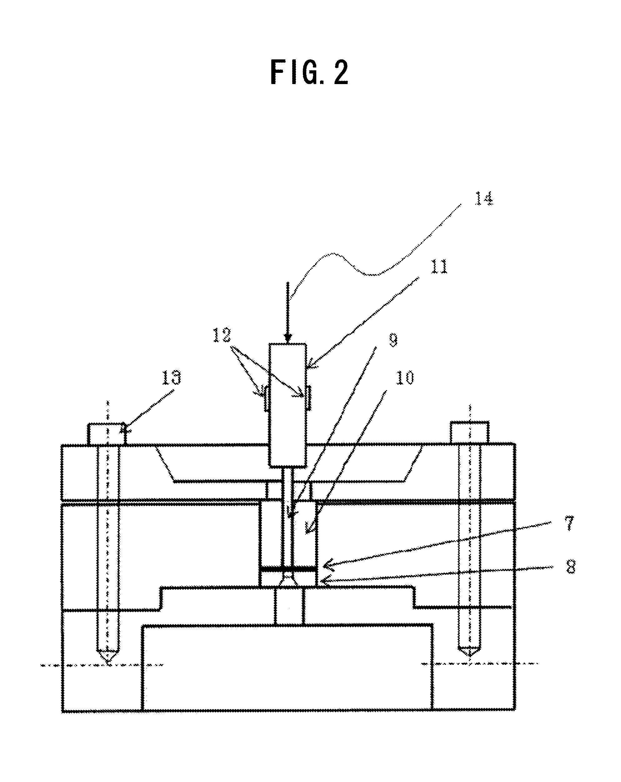
Image

Examples
Example
EXAMPLE
[0062]The effectiveness of the present invention will hereinafter be described in detail by referring to examples. The present invention are not limited to the examples shown below. It is of course possible to implement the present invention by making appropriate changes to the embodiment described above without departing from the scope of the invention. All of these variations are contained within the technical scope of the present invention. For example, the orifice plates in accordance with the embodiment of the present invention are not limited to those for injecting liquids, but applicable to other fluids, gases for example.
Example
Examples 1 to 3 and Comparative Example 1
[0063]The materials for Examples 1 to 3 were cold rolled stainless strips having the chemical compositions shown in Table 1(a). These strips made of JIS G4305 SUS304 No. 2B-finish cold rolled stainless steel had thickness of 3 mm. The materials were subjected repeatedly to cold rolling of 50% to 60% rolling reduction and to reverse transformation heat treatment so that the amount of stress-induced martensite generated by the cold rolling decreases to 5% or lower when measured using a ferrite content measuring instrument. The strips were processed into the thickness of 0.1 mm. By adjusting the final reverse transformation heat treatment conditions (temperature and time) as required, test materials having different average austenite crystal grain sizes were obtained and used for examples 1 to 3.
Example
[0064]The material for comparative example 1 to be described in this section is a JIS G4313 SUS304 ½-finish stainless steel strip for springs, namely a coiled cold rolled steel strip of chemical compositions shown in Table 1(b), having thickness of 0.1 mm and width of 20 mm.
TABLE 1CSiMnPSNiCr(a)0.060.401.090.0300.0048.0318.02(b)0.050.470.980.0280.0078.2118.20
[0065]Each test piece of coiled thin steel strips having plate thickness t of 0.1 mm and length of approximately 500 m prepared as described above for examples 1 to 3 and comparative example 1 was subjected to a tensile test, hardness test, structural observation by EBSP, and precision press punching test.
[0066]As described below, all of the examples 1 to 3 fall within the range of orifice plate for injecting liquids in accordance with the present invention. Details will be described below.
[0067](Material Test Method)
[0068]In the tensile test, test pieces obtained by cutting with the tensile direction coincided with the directio...
PUM
| Property | Measurement | Unit |
|---|---|---|
| Grain size | aaaaa | aaaaa |
| Grain size | aaaaa | aaaaa |
| Fraction | aaaaa | aaaaa |
Abstract
Description
Claims
Application Information
 - R&D
- Intellectual Property
- Life Sciences
- Materials
- Tech Scout
- Unparalleled Data Quality
- Higher Quality Content
- 60% Fewer Hallucinations
Browse by: Latest US Patents, China's latest patents, Technical Efficacy Thesaurus, Application Domain, Technology Topic, Popular Technical Reports.
© 2025 PatSnap. All rights reserved.Legal|Privacy policy|Modern Slavery Act Transparency Statement|Sitemap|About US| Contact US: help@patsnap.com