
Apparel with Reduced Drag Coefficient

a technology of drag coefficient and clothing, applied in the field of athletic apparel, can solve the problems of little can be done to streamline the form of an athlete to reduce drag, reduce the drag coefficient, and restrict the movement of the body, and achieve the effect of reducing drag

Active Publication Date: 2011-07-07
NIKE INC
View PDF21 Cites 13 Cited by
  • Summary
  • Abstract
  • Description
  • Claims
  • Application Information

AI Technical Summary

Benefits of technology

The invention provides a garment comprising a panel substantially encircling an appendage of a wearer, wherein the panel is configured to reduce drag on the appendage of the wearer from an oncoming fluid.
In another aspect, the invention provides a method for reducing drag on an athlete comprising the steps of: (i) providing an athletic garment comprising a panel substantially encircling an appendage of the athlete, the panel including at least two regions of surface texture of differing roughnesses; (ii) moving the appendage through a fluid to form a substantially laminar boundary layer flow around the athletic garment; and (iii) transitioning the boundary layer flow from laminar flow to turbulent flow at a critical velocity.

Problems solved by technology

Frictional drag is due to the friction between the fluid and the surfaces over which the fluid is flowing.
However, given that the shape of an athlete is not streamlined or optimized for motion through a fluid, the drag force on an athlete competing at high speeds is generally dominated by the pressure drag component.
An athlete may assume a crouching position in cycling or skiing to project a smaller frontal area to reduce pressure drag, but little can be done to streamline an athlete's form to reduce drag solely through training.
However, with certain types of bluff bodies, such as spheres and cylinders, it has long been known that increasing surface roughness of the bluff body can actually reduce the pressure drag.
However, in some high speed athletic events, such as cycling, the rules of the sport prohibit the wearing of non-essential garments or garments for the purpose of reducing drag.
As such, Z strips and body suits are not available to these athletes.

Method used


Image

  • Apparel with Reduced Drag Coefficient
  • Apparel with Reduced Drag Coefficient
  • Apparel with Reduced Drag Coefficient

Examples


Embodiment Construction

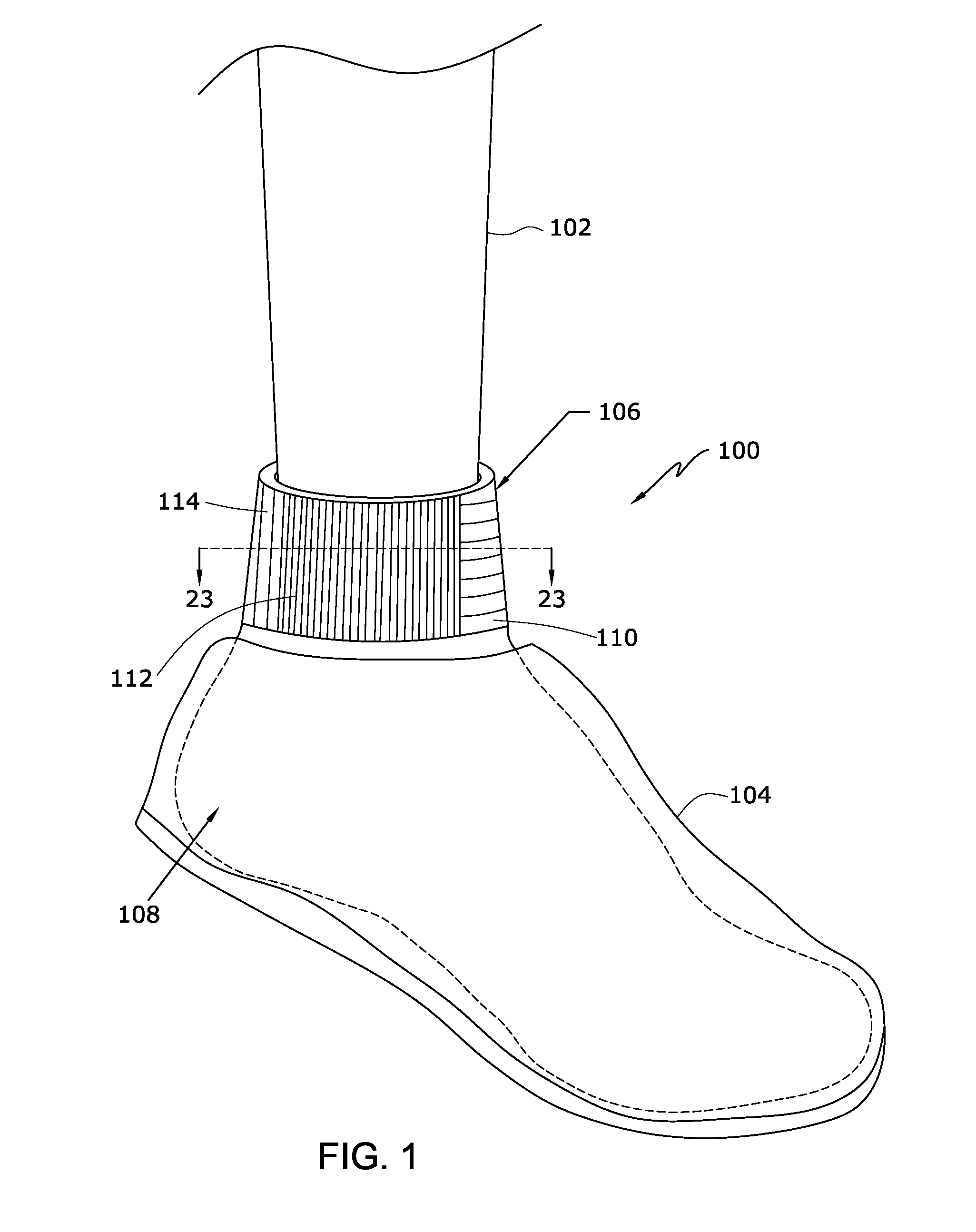
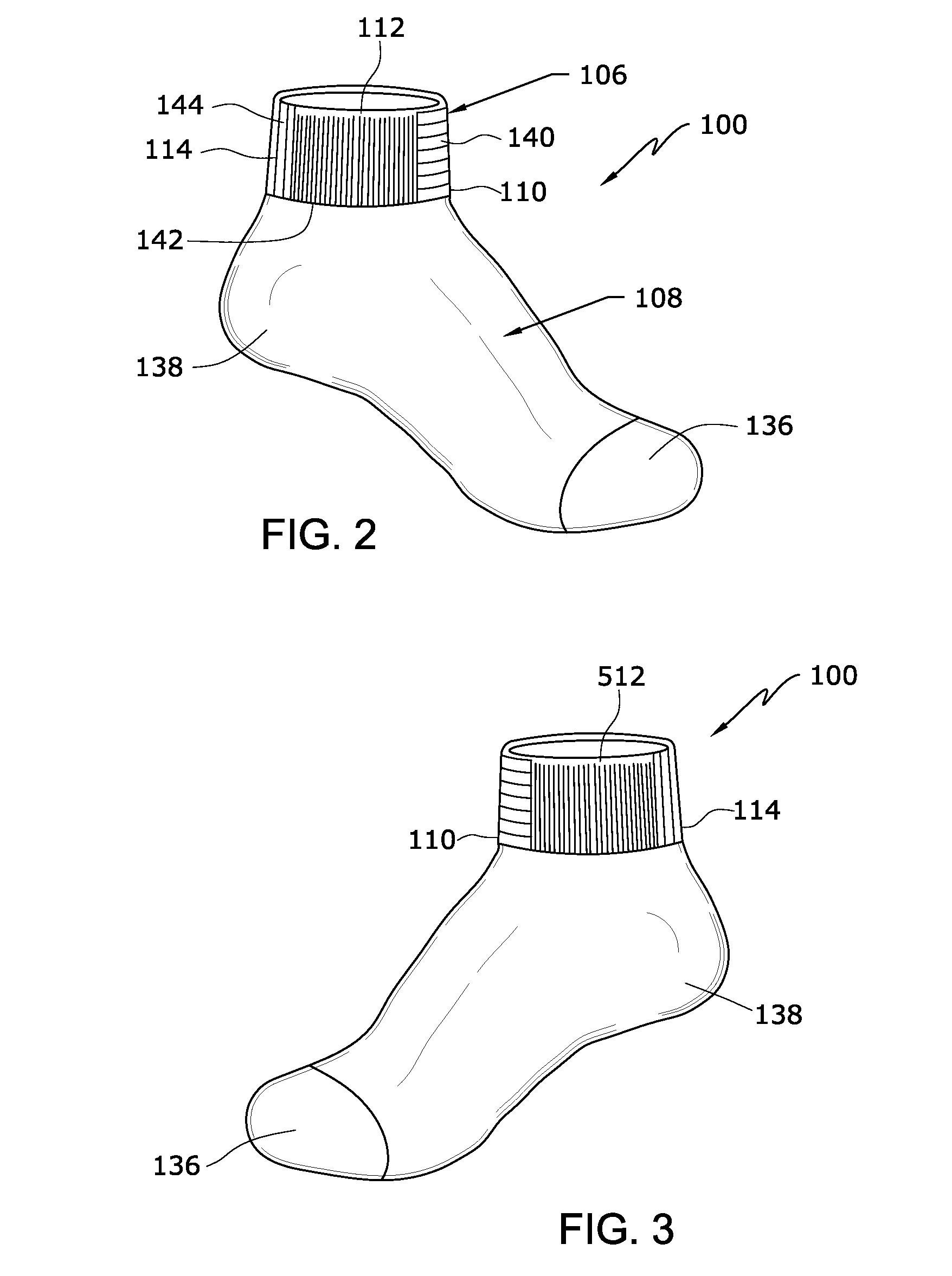
FIG. 1 is a schematic view of a portion of an appendage 102 of an athlete wearing an athletic garment 100 including a drag-reducing panel 106. In this embodiment, appendage 102 is a leg and athletic garment 100 is a sock. However, in other embodiments, appendage 102 may be any body part capable of being modeled as a substantially circular cylinder or sphere, for example, one or both legs, one or both arms, the head, the neck, and the like, and athletic garment 100 may be any type of garment that can encircle appendage 102, such as a wristband, headband, or sleeve. Optionally, a portion of appendage 102 and / or athletic garment 100 may be covered by an additional garment 104. In this embodiment, as appendage 102 is a leg, an optional shoe 104 is provided to cover the foot and a body portion 108 of athletic garment 100. Drag-reducing panel 106 is a cuff of the sock, configured to encircle the ankle region of appendage 102, forming an opening to provide access to body portion 108. Drag-...


PUM


Abstract

An athletic garment including a panel designed to reduce frictional and pressure drag around an appendage of an athlete competing in a high-speed event, such as running and cycling. The panel is positioned to encircle the appendage, and is provided with regions having different surface texture roughnesses. The leading edge of the panel includes texture designed to enhance the laminar boundary layer, while the adjacent portion of the panel includes texture intended to trip the boundary layer to turbulent flow. The drag-reducing panel may be the cuff of a sock, a sleeve, wristband, a headband, or the like.

Description

BACKGROUND OF THE INVENTION1. Field of the InventionThe present invention relates generally to athletic apparel, and in particular to athletic apparel for reducing the drag force on a wearer's appendage.2. Description of Related ArtIn many speed-based individual athletic events, such as bicycling, speed skating, and running, the difference between achieving first or second place is typically a fraction of a second. Individually-controllable factors, such as form and athletic power, are often the focus in the training for reducing performance time in such events. Drag due to the resistance of the movement of an athlete through a fluid such as the air or water is also a contributing factor in increasing performance time.Any body moving through a fluid experiences a drag force, which may be divided into two components: frictional drag and pressure drag. Frictional drag is due to the friction between the fluid and the surfaces over which the fluid is flowing. The smoother the surface, t...

Claims


Application Information

Patent Timeline
Patent Type & Authority Applications(United States)
IPC IPC(8): A41D13/00A43B17/00A41D1/00
CPCA41D13/05A41D13/0015A41D1/00A41D2400/24
Inventor WRIGHT, STEVEN P.CRAIG, KENNETH T.MACDONALD, RICHARD C.BROWNLIE, LEONARD W.
Owner NIKE INC
Learn More