Coordinate sensor, electronic device, display device, light-receiving unit

a technology of electronic devices and display devices, applied in the direction of instruments, computing, electric digital data processing, etc., can solve the problems of large manufacturing time and cost, difficult alignment, and complicated optical signal read-out circuits, so as to prevent unnecessarily large electronic display panels and save spa

Inactive Publication Date: 2011-06-30
SHARP KK
View PDF5 Cites 118 Cited by
  • Summary
  • Abstract
  • Description
  • Claims
  • Application Information

AI Technical Summary

Benefits of technology

[0111]In any of the above arrangements, the line sensors can be easily provided, outside the image display region, on the array substrate, and the electronic display panel can be prevented from unnecessarily becoming large.
[0112]In a case where the line sensors are provided in the sealing regions as described above, it is possible to save spaces for the line sensors, unlike the case where the line sensors are provided outside or inside the sealing regions. Meanwhile, in a case where the line sensors are provided inside or outside the sealing regions as described above, no stress is applied to the line sensors unlike the case where the line sensors are provided in the sealing regions although there is a disadvant

Problems solved by technology

In addition, an optical signal read-out circuit becomes complicated.
These problems are common among display devices with a two-dimensional sensor array.
However, the coordinate sensor disclosed in Patent Literature 3 has problems such as difficult alignment and large manufacturing time and cost since the detection

Method used


Image

  • Coordinate sensor, electronic device, display device, light-receiving unit
  • Coordinate sensor, electronic device, display device, light-receiving unit
  • Coordinate sensor, electronic device, display device, light-receiving unit

Examples


embodiment 1

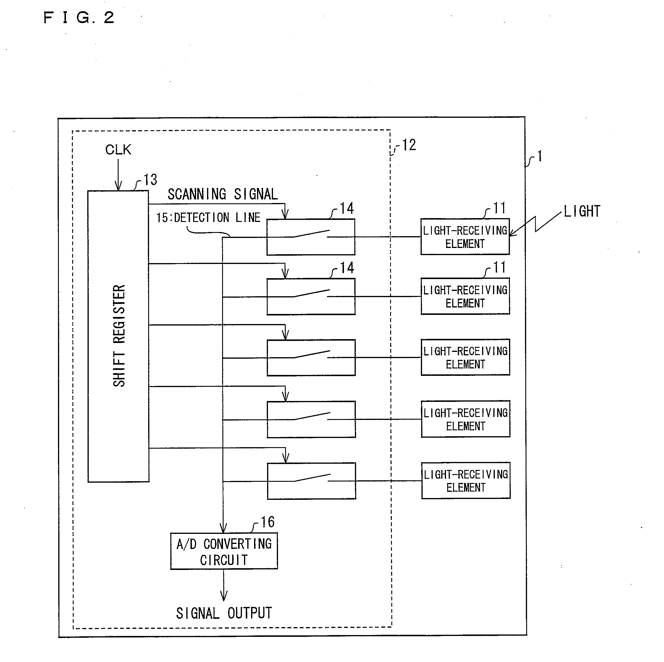
[0219]An embodiment of the present invention is described below with reference to (a) and (b) of FIG. 1 through FIG. 3.

[0220]The present embodiment deals with, as an example of an electronic device including a coordinate sensor, a liquid crystal display device with a built-in coordinate sensor (touch panel). The liquid crystal display device has, as a coordinate input function, a coordinate sensor function (touch panel function in the present embodiment).

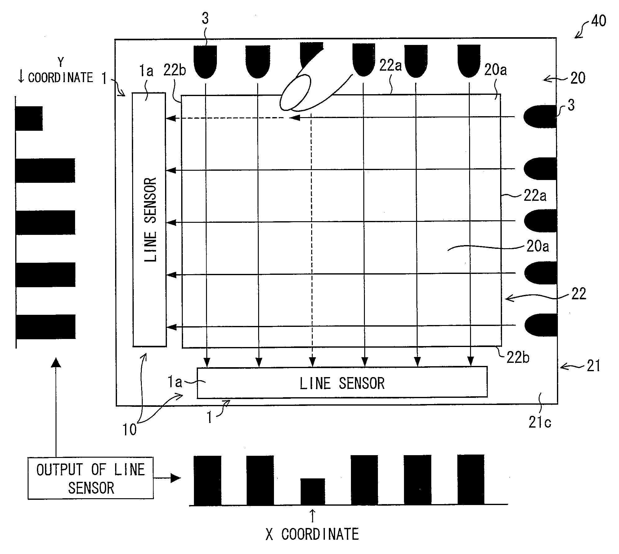
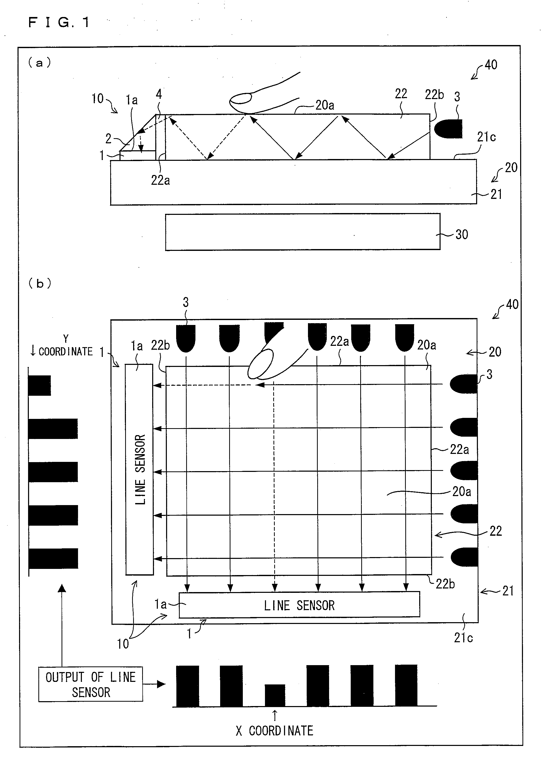
[0221](a) of FIG. 1 is a cross-sectional view schematically illustrating an outline configuration of a substantial part of the liquid crystal display device of the present embodiment. (b) of FIG. 1 is a plan view schematically illustrating, along with outputs of one-dimensional sensor arrays (hereinafter referred to as “line sensor”), (i) the outline configuration of the substantial part of the liquid crystal display device of the present embodiment and (ii) how a coordinate is detected in the liquid crystal display device.

[0222]As ...

embodiment 2

[0276]Another embodiment of the present invention is described below with reference to (a) and (b) of FIG. 4 through (a) and (b) of FIG. 7 and FIG. 25. The present embodiment discusses differences from the Embodiment 1, and constituents which have identical functions to those of the Embodiment 1 are given identical reference numerals, and are not explained repeatedly.

[0277]The Embodiment 1 has dealt with an example in which the infrared LEDs 3 for emitting light for detection of an coordinate position into the counter substrate 22 are provided in addition to the backlight 30. Meanwhile, the present embodiment deals with a case where the counter substrate 22 is irradiated with light for detection of a coordinate position from behind the liquid crystal panel 20.

[0278](a) of FIG. 4 is a cross-sectional view schematically illustrating an outline configuration of a substantial part of a liquid crystal display device of the present embodiment. (b) of FIG. 4 is a plan view schematically il...

embodiment 3

[0304]Another embodiment of the present invention is described below with reference to FIG. 8. Note that the present embodiment discusses differences from the Embodiments 1 and 2. Note also that constituents that have similar functions to those of the Embodiments 1 and 2 are given identical reference numerals, and are not explained repeatedly.

Each of the Embodiments 1 and 2 has dealt with an example in which a coordinate sensor 10 (line sensors 1 and right angle prisms 2) is provided so as to face an end surface (edge section) of a counter substrate 22. Meanwhile, the present embodiment deals with a case where a coordinate sensor is provided so as to overlap a counter substrate 22.

[0305]FIG. 8 is a cross-sectional view schematically illustrating an outline configuration of a substantial part of a liquid crystal display device 40 of the present embodiment.

[0306]As illustrated in FIG. 8, a coordinate sensor 60 of the present embodiment includes, as light path changing means (light pat...


PUM


Abstract

A coordinate sensor (10) includes at least two line sensors (1) that are disposed in x-axis and y-axis directions, and right-angle prisms (2) each of which changes a light path of light that has passed through an image display region of a liquid crystal panel (20). Each of the line sensors (1) is disposed outside the image display region and has a light-receiving surface (1a) parallel to an image display surface of the liquid crystal panel (20). The right angle prisms (2) cause light which travels in the x-axis and y-axis directions and which has passed through the image display region to be guided to the light-receiving surfaces (1a) of the line sensors (1). The coordinate sensor (10) receives the light which has thus passed through the image display region of the liquid crystal panel (20) so as to detect a coordinate, on the image display region, that is indicated by an object to be detected such as a finger. Consequently, a thin coordinate sensor that enables easy alignment with no reduction in aperture ratio and no restriction on operation speed can be realized at low cost.

Description

TECHNICAL FIELD[0001]The present invention relates to (i) a coordinate sensor which detects, based on received light which has passed through an image display region of an image display member, a coordinate, on the image display region, indicated by an object to be detected, (ii) an electronic device including the coordinate sensor, (iii) a display device including the coordinate sensor, (iv) a liquid crystal display device with a built-in coordinate sensor, and (v) a light-receiving unit that can be suitably applied to the coordinate sensor.BACKGROUND ART[0002]Various kinds of display devices such as liquid crystal display devices have been developed. Such display devices include display devices with a touch panel that have a touch panel (coordinate sensor) function, i.e., are capable of detecting a position, of a panel surface, touched by a finger or an input pen.[0003]As such display devices with a touch panel, display devices with a so-called resistive touch panel and display de...

Claims


Application Information

Patent Timeline
IPC IPC(8): G06F3/042
CPCG02F1/13338G06F2203/04109G06F3/0428G06F3/0421
Inventor HAMADA, HIROSHIMIYAZAKI, SHINICHINOMA, MIKIHIROTAKAHAMA, KENGOWADA, MASAKAZUHOHSHI, NORIKAZUODA, KOHICHIMIZUNO, YUKIO
Owner SHARP KK
Why Eureka
Try Eureka