Bonding apparatus

Active Publication Date: 2011-06-30
SHINKAWA CO LTD
View PDF4 Cites 6 Cited by
  • Summary
  • Abstract
  • Description
  • Claims
  • Application Information

AI Technical Summary

Benefits of technology

[0016]The present invention offers the advantage of detecting a vibration load at a tip end of a bonding tool in a simply structured bonding apparatus.

Problems solved by technology

Also, in the related arts described in both Japanese Unexamined Patent Application Publication No. 10-256320 and Japanese Patent No. 3530139, the load sensor is attached at a site of the ultrasonic horn at which the amplitude of ultrasonic vibration emerges, suffering from a problem in that the sensor attached to the ultrasonic horn affects the ultrasonic vibration and thereby has some impact on the bonding performance.
Further, changing the ultrasonic horn as appropriate also requires the sensor to be changed, suffering from a problem of taking a long time for maintenance because it is necessary to make an adjustment such as a calibration at every change of the ultrasonic horn.

Method used


Image

  • Bonding apparatus
  • Bonding apparatus
  • Bonding apparatus

Examples


Embodiment Construction

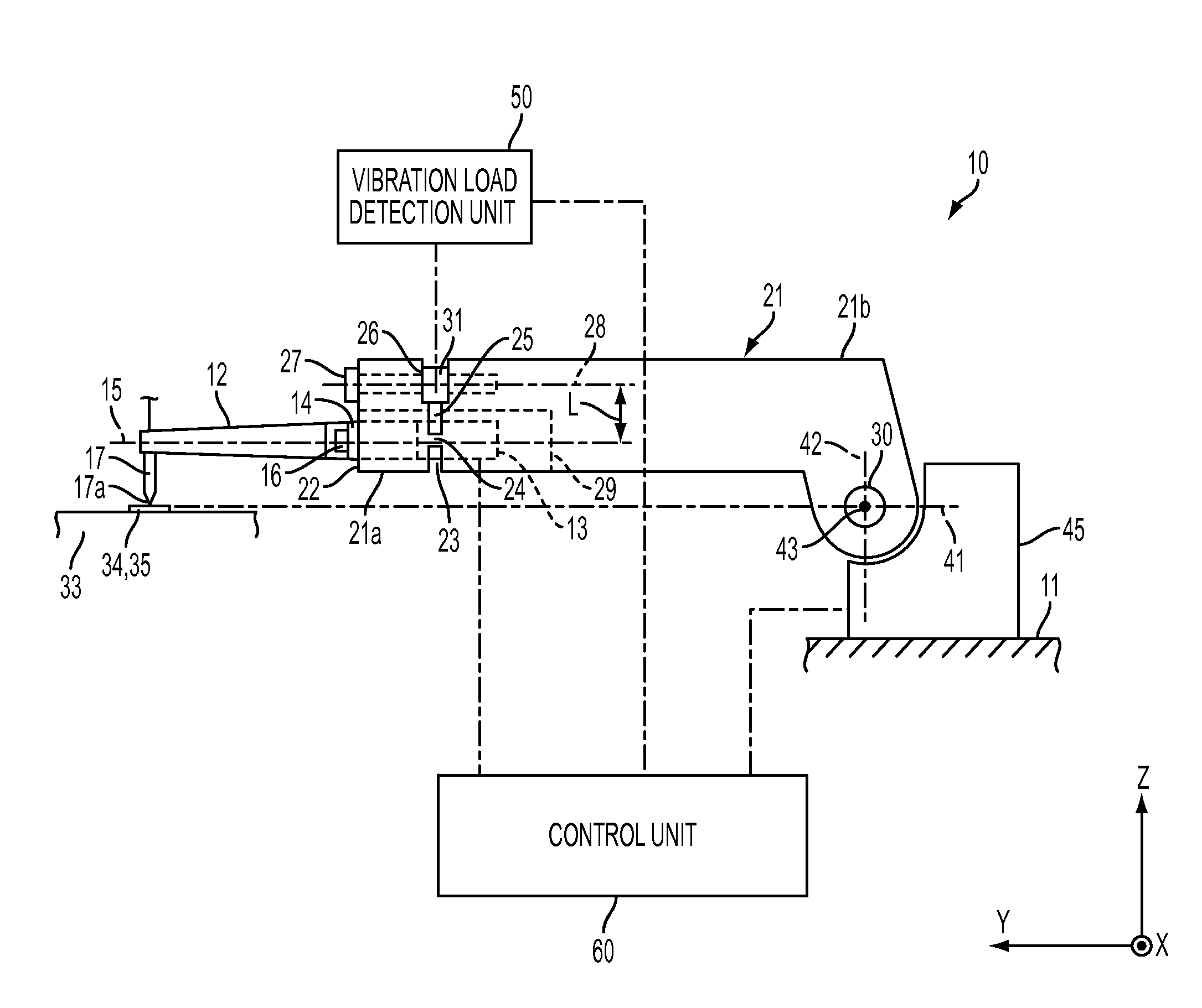
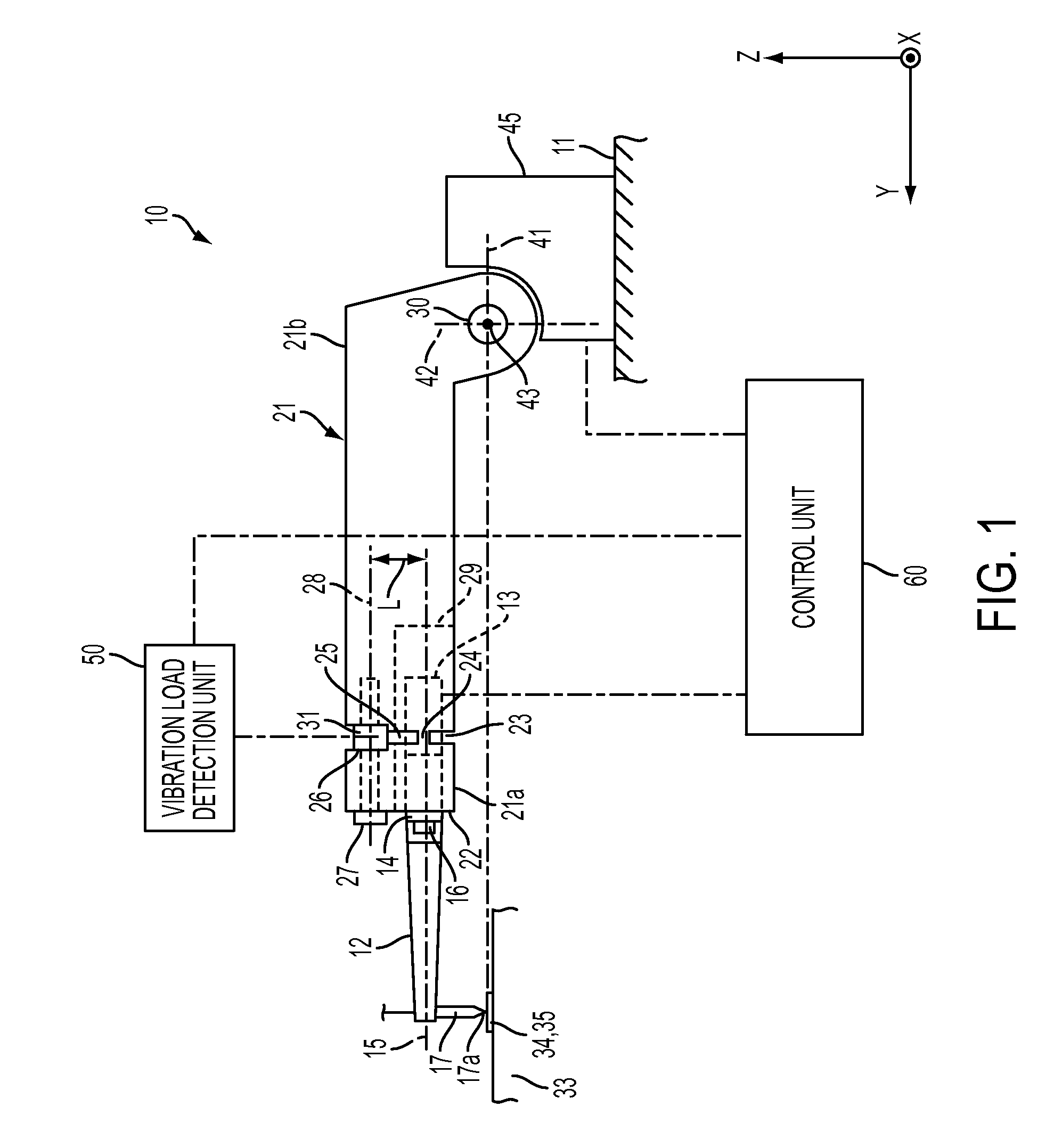
[0026]Exemplary embodiments of the present invention will hereinafter be described in detail with reference to the accompanying drawings. As shown in FIG. 1, a wire-bonding apparatus 10 according to this exemplary embodiment includes a bonding head 11 serving as a base unit, an ultrasonic vibrator 13, an ultrasonic horn 12, a capillary 17 serving as a bonding tool, a flange 14 provided on the ultrasonic horn 12, a bonding arm 21, a load sensor 31, a drive motor 45, a vibration load detection unit 50, a control unit 60, and a bonding stage 33 on which a semiconductor chip 34 or a substrate 35 is absorbed and fixed as a bonding target.

[0027]The drive motor 45 for rotating the bonding arm 21 is provided on the bonding head 11. The ultrasonic vibrator 13 is formed by overlaying multiple piezoelectric elements and attached at the rear end of the ultrasonic horn 12. The capillary 17 is attached at one end of the ultrasonic horn 12. The flange 14 is provided at a node of the vibration of t...


PUM

PropertyMeasurementUnit
Stabilityaaaaaaaaaa

Abstract

A bonding apparatus includes an ultrasonic horn configured to vibrate longitudinally in resonance with the vibration of an ultrasonic vibrator; a capillary attached at an anti-node of the vibration of the ultrasonic horn; a flange provided at a node of the vibration of the ultrasonic horn; a bonding arm; a load sensor attached between the center of rotation of the bonding arm and a flange mounting surface; and a vibration load detection unit for extracting a signal obtained by causing a signal that is detected with the load sensor to pass a signal within a frequency range around the vibrational frequency of the ultrasonic vibrator through a band-pass filter, whereby the bonding apparatus can detect the vibration load at a tip end of the capillary in the direction along the central axis of the ultrasonic horn with a simple structure.

Description

BACKGROUND OF THE INVENTION[0001]1. Field of the Invention[0002]The present invention relates to a structure of a bonding apparatus.[0003]2. Related Art[0004]In semiconductor manufacturing processes, wire-bonding apparatuses are often used for bonding of thin metallic wires to electrode pads on a semiconductor chip and electrode leads on a lead frame for connection therebetween. Many wire-bonding apparatuses include a bonding arm configured to be rotated by a drive motor, an ultrasonic horn attached to the bonding arm, a capillary attached at one end of the ultrasonic horn, and an ultrasonic vibrator attached to the ultrasonic horn. In such wire-bonding apparatuses, the bonding arm is driven and rotated to move the capillary in a direction toward and away from a pad or lead and to bond an initial ball formed at a tip end of the capillary or a wire to the pad or lead, and then the ultrasonic horn is resonated with the ultrasonic vibrator to provide ultrasonic vibration at the tip end...

Claims


Application Information

Patent Timeline
IPC IPC(8): B23K1/06
CPCB23K20/007B23K2201/42H01L2924/014H01L24/78H01L24/85H01L2224/78301H01L2224/789H01L2224/85205H01L2224/85206H01L2924/01004H01L2924/01033H01L2924/01082H01L2924/00014H01L2924/01005H01L2924/01006H01L2224/48H01L2224/451B23K2101/42H01L2924/00H01L2224/45099H01L2224/05599
Inventor AOYAGI, NOBUYUKISEYAMA, KOHEI
Owner SHINKAWA CO LTD
Why Eureka
Try Eureka