Reticle POD and supporting components therebetween

Active Publication Date: 2011-06-30
GUDENG PRECISION IND CO LTD
View PDF10 Cites 11 Cited by
  • Summary
  • Abstract
  • Description
  • Claims
  • Application Information

AI Technical Summary

Benefits of technology

[0008]Another primary object of the present invention is to provide a reticle POD disposed with a plurality of supporting components, in which the design of leading elements of the supporting components allow the reticle to be precisely placed into the position for mounting.
[0009]Still another primary object of the present invention is to provide a metal reticle POD that prevents the reticle from being damaged by the ESD or EMI.
[0010]Yet another primary object of the present invention is to provide an airtight reticle POD to isolate the reticle in the reticle POD from air in the exterior to increase the lifetime of reticle.
[0014]By applying the design provided by the present invention, the reticle can thus be smoothly and easily led into and effectively mounted to the reticle POD, and the function of preventing from ESD and EMI can also be provided. In addition, the reticle POD disclosed by the present invention can also provide an airtight space to protect the reticle and prevent from haze formation and thus increase the lifetime of the reticle.

Problems solved by technology

In modern advanced Foundries or semiconductor Fabs, the level at 90 nm and below process has been achieved in the chip manufacturing process; therefore, the size of pattern on the reticle for lithography process has to be reduced and the width of lines in the pattern needs to be small, and the production cost is thus very high.
However, there are two defects in the design of the supporting components.
One defect is that the supporting components are fixedly integrated with the reticle POD and each supporting component has a rigid body and lacks cushion-like property.
Thus when the reticle POD is dashed or falls down, the impact force will pass through the supporting components and directly to the reticle and may cause partial damage or shattering of the reticle.
The other defect is that the design of individual supporting component makes it easier for the reticle to be displaced and thus damaged when the reticle is placed into the POD due to lack of proper leading device.
Furthermore, due to the advancement of the process, in the processes of higher level in Fabs, EMI in Fabs, in addition to electrostatic effect, will also cause damage to the reticle, particularly when the reticle is in the stage of being stored or in the lithography process and changes in the surroundings are hard to predict.

Method used


Image

  • Reticle POD and supporting components therebetween
  • Reticle POD and supporting components therebetween
  • Reticle POD and supporting components therebetween

Examples


Embodiment Construction

[0023]As what is disclosed in the present invention is a reticle POD disposed with a plurality of supporting components, the major improvement lies in the portion of supporting components, and the other detailed procedures in the reticle or reticle POD manufacturing or processing processes, including the procedures of forming reticle POD made of polymer material or of metal, are accomplished by utilizing the current technology. Therefore in the following description, the details of reticle or reticle POD manufacturing or processing processes are not completely described. And the drawings referred to in the following are not made according to the actual sizes as the function of which is only to illustrate characteristics of the present invention.

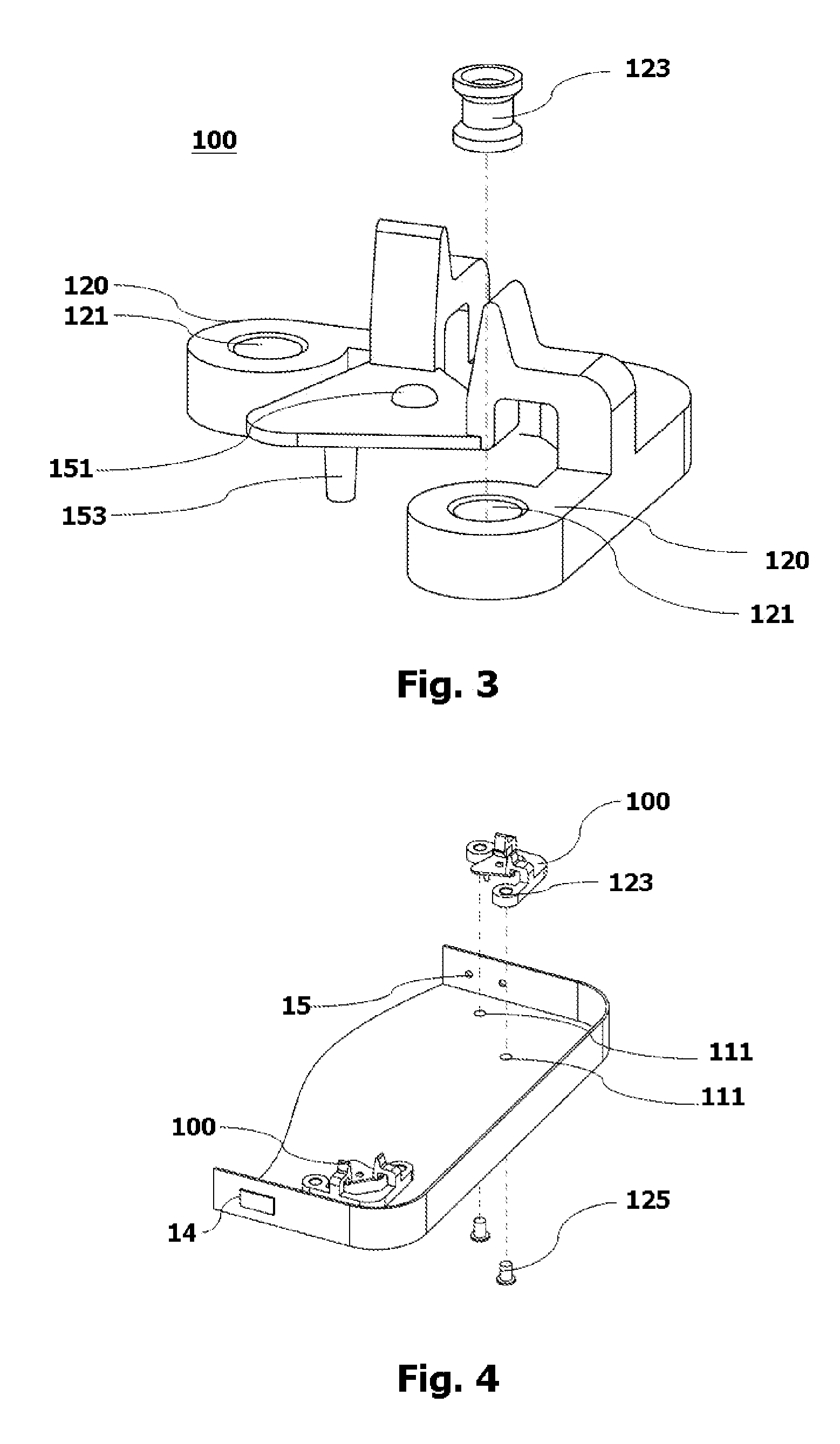
[0024]First, referring to FIG. 2, which is a view of the supporting components disposed in the reticle POD of the present invention. As shown in FIG. 2, the supporting component 100 comprises: a base body, assembled by two supporting arms 110...


PUM


Abstract

A reticle POD, comprising a top cover, a bottom cover, and a plurality of supporting components deployed in the four corners of the bottom cover, the supporting component comprising: a base body perpendicularly assembled, on two sides of which being disposed with mounting blocks; a pair of elastic elements respectively placed on the base body; a pair of leading elements connecting respectively to the horizontal extension of the elastic elements and then extending lengthwise to form a tip, a first bevel and a second bevel being formed on the side of the tip located on the inner side of the base body; a supporting base plate, the first and the second ends of which being connected to the second bevel of the leading element and a supporting pillar being disposed on the third end of the supporting base plate.

Description

BACKGROUND OF THE INVENTION[0001]1. Field of the Invention[0002]The present field of the invention is related to a reticle POD, and more particularly, to the structure of a reticle POD disposed with a plurality of supporting components.[0003]2. Description of the Prior Art[0004]In modern advanced Foundries or semiconductor Fabs, the level at 90 nm and below process has been achieved in the chip manufacturing process; therefore, the size of pattern on the reticle for lithography process has to be reduced and the width of lines in the pattern needs to be small, and the production cost is thus very high. In order to reduce the high production cost of reticle, modern advanced Foundries or Fabs, especially Foundries or Fabs manufacturing memory products, manage to increase the lifetime of reticle.[0005]Due to needs in the manufacturing process, it is often needed for the reticle to be transferred to and fro between the storage box and the lithography tool. Therefore, the reticle needs to...

Claims


Application Information

Patent Timeline
IPC IPC(8): B65D25/02
CPCG03F1/66H01L21/67373H01L21/67359H01L21/67353
Inventor LU, PAO-YIWANG, SHENG-HUNG
Owner GUDENG PRECISION IND CO LTD
Why Eureka
Try Eureka