System and process for simulation or test exploiting data from monitoring ports

Inactive Publication Date: 2011-06-23
AIRBUS OPERATIONS SAS
View PDF6 Cites 11 Cited by
  • Summary
  • Abstract
  • Description
  • Claims
  • Application Information

AI Technical Summary

Benefits of technology

[0021]The third switch makes it possible to distribute a copy of messages being broadcast on the network without additional processing either from the simulation unit or from any other active equipment item of the network.
[0032]In one embodiment, the third switch presents a plurality of sets of output ports identically duplicating the data of all of the input ports, and another set of configurable output ports for generating outputs that concatenate and / or filter several input ports. The configuration here makes it possible to satisfy both the needs of time-invariant applications for which all of the data of the monitored ports are transmitted (for example, the simulation unit, which identically recovers all of the messages) and the more specific and more temporary needs of particular tools. Again, the aggregation of several inputs for one output satisfying these specific needs efficiently uses the resources of the switch and especially the number of output ports.

Problems solved by technology

However, this solution leads to an additional processing load for the simulation unit.
In addition, since all of the messages are necessary for the tools, the simulation unit must then acquire the real inter-computer messages (which are therefore not necessarily used by the simulation models), further increasing its processing load.
Nevertheless, such acquisition must be performed on all the segments of the network on which a given message may transit, and it therefore produces numerous duplicates of messages.
This also results in a nonproductive overload for the acquisition equipment as well as in possible processing operations aimed at suppressing the duplicates before transmission to the tools.

Method used


Image

  • System and process for simulation or test exploiting data from monitoring ports
  • System and process for simulation or test exploiting data from monitoring ports
  • System and process for simulation or test exploiting data from monitoring ports

Examples


Embodiment Construction

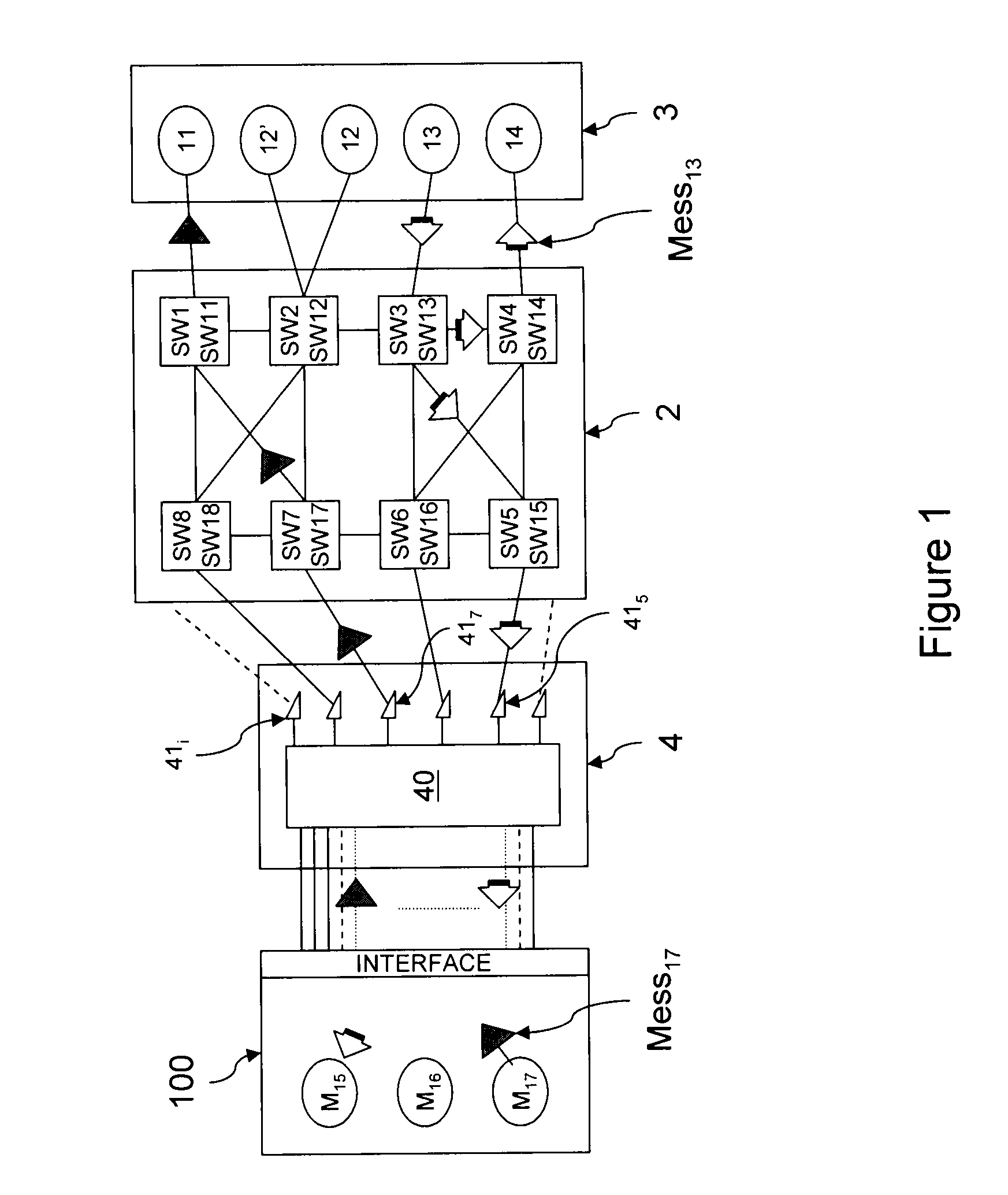
[0043]An ADCN network intended to equip an aircraft and having specifications adapted to the air domain has been shown on FIG. 1. This network is based on the AFDX communication technology, whose prerequisites pertaining to service quality are intended to assure real-time use.

[0044]This network 2, which is referred to hereinafter as AFDX network in conjunction with the associated communication technology, interconnects a plurality of on-board equipment items 11, 12, 12′, 13, 14 with one another, or in other words equipment items performing functions specific to the aircraft, such as an automatic pilot, speed transducers and altimeters, etc. These on-board equipment items are also referred to as computers or LRUs (“Line Replaceable Units”), and they define domain 3 of real computers, which in practice comprise several dozen computers. In the on-board systems, it is common practice for the computers to be duplicated for issues of safety. Nevertheless, each redundant computer is a sepa...


PUM


Abstract

The present invention relates to a system for simulating / testing an aeronautic computer network architecture, especially installed on board an aircraft, and to a corresponding method.The system comprises:a communication network (2) comprising a plurality of switches (SW1-SW8);a plurality of real computers (11-14) connected to the network at the corresponding switches (SW1-SW4);a simulation unit (100) simulating at least one computer (15-17) of the said architecture and connected to the network at at least one corresponding switch (SW5-SW8), anda third switch (42), which receives, at input ports (PE), data (Mess13, Mess17) acquired at the monitoring ports (PM) of the said corresponding switches and emitted by the said computers over the network, the third switch being configured to duplicate the said data over a plurality of output ports (UTAPj OB1j, AFDXIFj, OTij), to which a plurality of consuming applications (100, 110, UTAP, OBi, OTi) is connected.

Description

FIELD OF THE INVENTION[0001]The present invention relates to a system for simulating or testing an aeronautic computer network architecture, especially installed on board an aircraft, and to a corresponding method.BACKGROUND OF THE INVENTION[0002]The development of real systems is currently achieved progressively with the aid of simulation systems. These systems make it possible not only to visualize and test projects in progress but also to make them evolve rapidly and at lower costs.[0003]This is the case in particular in the aeronautic sector, where there are used simulation systems in which on-board equipment items, also known as real computers or LRUs (“Line Replaceable Units”), are integrated with modules simulating other on-board equipment items.[0004]In the recent aircraft versions, the real computers are integrated into a digital network architecture of Ethernet type adapted to aeronautics and known as ADCN (“Avionics Data Communication Network”), which uses the AFDX techno...

Claims


Application Information

Patent Timeline
IPC IPC(8): G06F11/07
CPCH04L12/2697H04L41/145H04L49/206H04L49/201H04L43/50
Inventor CANDIA, FABRICE
Owner AIRBUS OPERATIONS SAS
Why Eureka
Try Eureka