
Method for testing an optical investigation system

a technology of optical investigation and optical probe, applied in the field of optical investigation system testing, can solve the problems of frequent failure of sources, influence of endoscopy system functionality, source subject to alteration process,

Active Publication Date: 2011-06-23
KARL STORZ GMBH & CO KG
View PDF21 Cites 19 Cited by
  • Summary
  • Abstract
  • Description
  • Claims
  • Application Information

AI Technical Summary

Benefits of technology

[0017]In a light-sensitive image sensor (for example, CCD or CMOS sensor), as a rule, both the exposure time and the analog gain of the electric signals can be selected before their digitization. The longest possible exposure time is thus predetermined by the image repetition frequency. If the image generated by the imaging lens on the image sensor is bright, a short exposure time and a low or minimal gain are selected. With decreasing image brightness, the exposure time is extended, for example, at first at unchanged low gain, to achieve the lowest possible noise. The longest possible exposure time at an image repeating frequency of 50 Hz (50 whole or half images per second) amounts to something less than 20 ms. If the exposure time cannot be further extended, the gain is increased. Thus with decreasing brightness of the image on the image sensor, the noise increases or the signal-noise distance in the signal of the image sensor decreases. When the gain has reached a maximum value with decreasing brightness of the image on the image sensor, only the brightness values of the digitized image can still be numerically scaled. Consequently, with further decreasing brightness the image quality is drastically reduced.
[0049]In every one of the methods described here, in addition, patient data can be recorded and information on the functionality or on another property of the optical investigation system and the patient data can be filed in a database. By integrating the test method with the recording and storage of patient data, it is possible to ensure that with every medical-diagnostic application of the optical investigation system, said system is tested with respect to its functionality and / or to another property and the result of the testing is documented individually or in relation to the patient. The test method can thus become a reliable, non-manipulatable component of quality assurance in everyday clinical practice.

Problems solved by technology

Frequent sources of failure are, among others, the light source subjected to an alteration process, possibly the light conductor cable and its coupling to the light source and the endoscope, and the coupling of a video camera to the endoscope.
The aforementioned sources of failure or influences on functionality of the endoscopy system include, in the case of observation of fluorescence, the combination of the illumination filter or spectrum of the light source on the one hand and of the observation filter on the other hand.
A corresponding problem exists with other optical investigation systems, which include an imaging device, a light source and a video camera for optical investigation of medical and non-medical objects in remitted light and / or in fluorescent light.
For example, under some conditions and for a few applications none of the described apparatuses and methods allows a reliable testing of a complete endoscopy system or of a different complete optical investigation system in precisely the condition in which it was used or is used medically or non-medically before or afterward.
A disadvantage of the apparatuses and methods described in DE 196 38 809 A1 and in DE 198 55 853 A1 consists in the fact that the video camera automatically post-controls a minor erroneous image brightness, so that it is partially or completely compensated by the camera system and only at very reduced lighting does the image become recognizably poor.
In particular in fluorescent diagnostics, however, the risk of an incorrect diagnosis, in particular the overlooking of a tumor, exists immediately beforehand.

Method used


Image

  • Method for testing an optical investigation system
  • Method for testing an optical investigation system
  • Method for testing an optical investigation system

Examples


Embodiment Construction

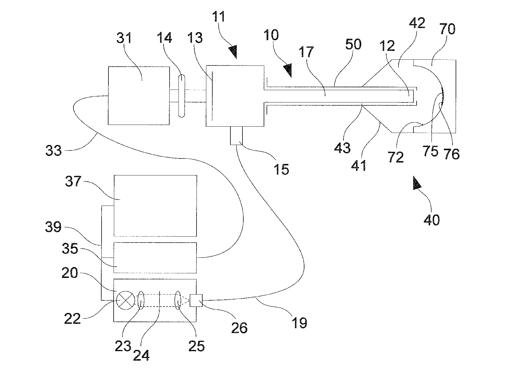
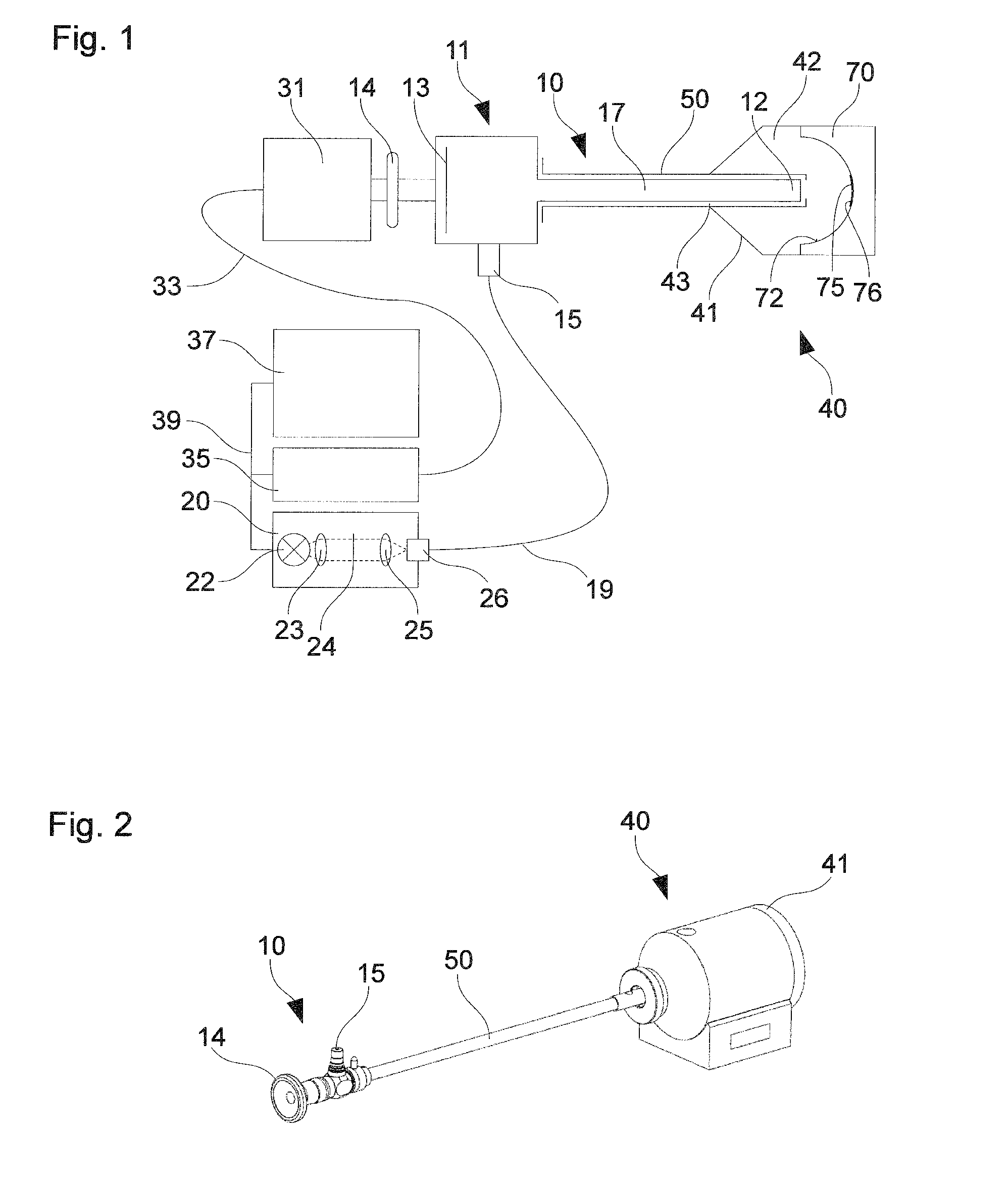
[0062]FIG. 1 shows a schematic depiction of an optical investigation system. The optical investigation system in this example is an endoscopy system, which can be applied, for example, in medical-diagnostic methods in urology and in other specialties. The endoscopy system includes an endoscope 10 with a proximal end 11 and a distal end 12. The endoscope 10 includes an illumination or excitation beam path and an observation beam path, which are not shown in detail in FIG. 1. The illumination beam path includes in particular one or more lightwave conductors to transmit illumination or excitation light from the proximal end 11 to the distal end 12 and a light outlet on the distal end 12 through which illumination light can exit from the distal end 12 of the endoscope 10 in order to illuminate an object to be observed. The observation beam path includes a light inlet on the distal end 12 of the endoscope 10, a lens to transmit observation light emitted from an observed object, from the ...


PUM


Abstract

A method for testing an optical investigation system, with an imaging device, a video camera and a light source for optical investigation of an object, a reference surface with predetermined optical properties is illuminated with illuminating light from a light source. An image of the reference surface is recorded by the imaging device and the video camera. An operating condition of the video camera that prevails during the recording of the image is recorded. The functionality or another property of the investigation system is determined on the basis of the recorded operating condition.

Description

CROSS-REFERENCE TO RELATED APPLICATIONS[0001]The present application claims priority of German patent application No. 10 2009 058 662.8 filed on Dec. 16, 2009.FIELD OF THE INVENTION[0002]The present invention relates to a method for testing an optical investigation system, with a light source, an imaging device and a video camera, for optical investigation of an object both within and outside the field of medicine. The present invention relates in particular to a method for testing an endoscopy system with a light source, an endoscope and a video cameraBACKGROUND OF THE INVENTION[0003]Endoscopy systems, consisting of an endoscope and a light source, are used for endoscopy in medical or non-medical applications—in the latter case also known as boroscopy. The light source can be integrated in the endoscope, in particular in its distal end, or can be present as a separate unit, which is optically coupled with an endoscope by a light conductor cable. Light from the light source emerges ...

Claims


Application Information

Patent Timeline
IPC IPC(8): H04N7/18
CPCA61B1/00057A61B5/0059A61B5/1495A61B1/043G01N21/274G01N21/6447G01N21/6456A61B2560/0233A61B1/00186
Inventor BECK, GERDEHRHARDT, ANDREMARTIN, UWEGLOEGGLER, BERNHARDSCHACHENMAYR, HILMARKENNEDY, BRYANCOUSSA, RAYMONDTANG, NATHAN
Owner KARL STORZ GMBH & CO KG
Learn More