Fast analysis method of steady-state fields, fast analysis program of steady-state fields, and recording medium
a steady-state field and analysis program technology, applied in the direction of computation using non-denominational number representation, design optimisation/simulation, instruments, etc., can solve the problem of inability to correct a physical quantity of an analysis object, reducing the primary effect of the tp-eec method to obtain a steady-state field fast, and inability to correct the calculation cost (calculation time) for correction, etc. problem, to achieve the effect of steady-state field and lower cost calculation
- Summary
- Abstract
- Description
- Claims
- Application Information
AI Technical Summary
Benefits of technology
Problems solved by technology
Method used
Image

Examples
first embodiment
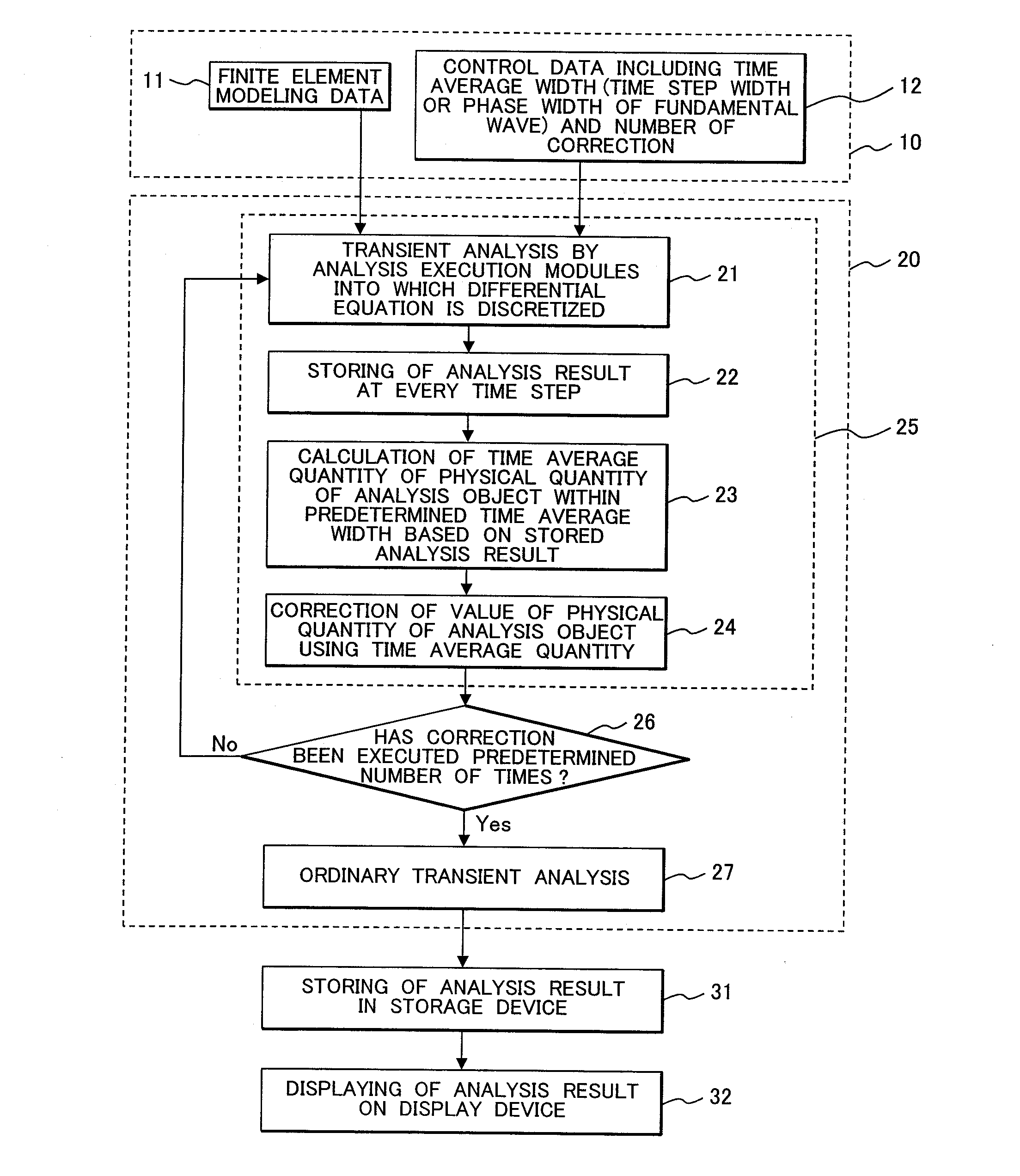
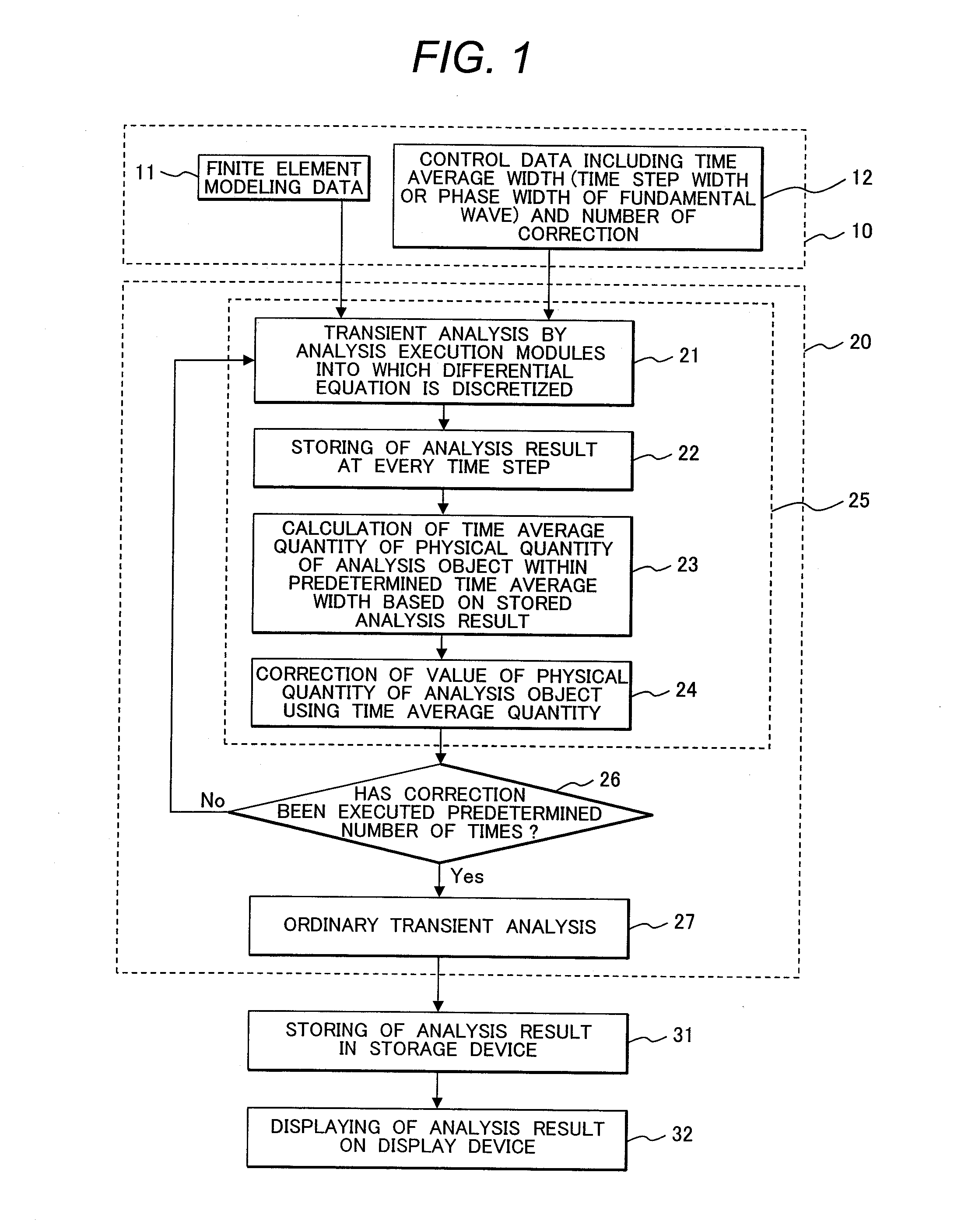
[0018]Referring to FIG. 1, a fast analysis method of steady-state fields of the first embodiment in accordance with the present invention will be described below. FIG. 1 shows processes of analysis based on the fast analysis method of steady-state fields according to the present embodiment. The processes of analysis include a process of reading input data 10, an analysis process 20, a storing 31 of analysis results, and a displaying 32 of analysis results. The processes will be described below.
[0019]In the process of reading the input data 10, a computer read the input data 10. The input data 10, which is stored in a data file, includes finite element modeling data (mesh data) 11 of an analysis object for numerically solving a differential equation, and control data 12 for controlling the analysis process. The control data 12 includes at least one of a time average width for time averaging on a physical quantity of the analysis object, a phase width of a fundamental wave correspondi...
second embodiment
[0032]As the second embodiment of the fast analysis method of steady-state fields in accordance with the present invention, an embodiment about the correction 24 of a physical quantity of an analysis object described in the first embodiment will be described. The correction 24 of a physical quantity is executed using the time-averaged physical quantities of the analysis object obtained by executing the calculation 23 of time-averaged quantities.
[0033]As described in the first embodiment, once one of the values of the time step width m, the time average width mΔt, and the phase width ωmΔt of the fundamental wave is given, the other two values thereof can be obtained using the time step size Δt and the angular frequency ω of the fundamental wave.
[0034]For convenience in explanations, a description will be made concerning one variable field x(t), where t denotes a time. If a steady-state field is half-periodic, that is, if a condition x(t+T / 2)=−x(t) is satisfied, where T denotes a peri...
third embodiment
[0048]A fast analysis method of steady-state fields of the third embodiment in accordance with the present invention employs another calculation method of a time derivative in the fast analysis method of steady-state fields of the second embodiment.
[0049]Differentiating the equation (9) once with respect to the phase θ leads to the following equation:
θ〈x1(θ)〉=(sinϕ / 2ϕ / 2)[a1cos(θ-ϕ2)-b1sin(θ-ϕ2)].(22)
Using the equations (10) and (22), two equations of x1 are obtained as follows:
x1(θ)=-(ϕ2)[cot(ϕ2)2θ2〈x1(θ)〉-θ〈x1(θ)〉](23)x1(θ-ϕ)=-(ϕ2)[cot(ϕ2)2θ2〈x1(θ)〉+θ〈x1(θ)〉].(24)
The equations (23) and (24) lead to corrections expressed by the following equations:
xnew(θ)=-(ϕ2)[cot(ϕ2)2θ2〈xold(θ)〉-θ〈xold(θ)〉](25)xnew(θ-ϕ)=-(ϕ2)[cot(ϕ2)2θ2〈xold(θ)〉+θ〈xold(θ)〉].(26)
When time axes of the equations (25) and (26) are discretized,
xn-1new=-ϕ2(m+1)×[cot(ϕ / 2)(ωΔt)2(∑k=n-mnxkold-2∑k=n-m-1n-1xkold+∑k=n-m-2n-2xkold)-12ωΔt(∑k=n-mnxkold-∑k=n-m-2n-2xkold)](27)xn-m-2new=-ϕ2(m+1)×[cot(ϕ / 2)(ωΔt)2(∑k=n-mnxkold-2∑k=n-m...
PUM
 Abstract
Description
Claims
Application Information
 - R&D
- Intellectual Property
- Life Sciences
- Materials
- Tech Scout
- Unparalleled Data Quality
- Higher Quality Content
- 60% Fewer Hallucinations
Browse by: Latest US Patents, China's latest patents, Technical Efficacy Thesaurus, Application Domain, Technology Topic, Popular Technical Reports.
© 2025 PatSnap. All rights reserved.Legal|Privacy policy|Modern Slavery Act Transparency Statement|Sitemap|About US| Contact US: help@patsnap.com