
Adaptive shading in a graphics processing pipeline

a graphics processing pipeline and adaptive shading technology, applied in the field of graphics processing, can solve the problems of reducing the realism of the 2-d image, limiting the design of these gpus also limits the types of tasks that the gpu can perform, so as to reduce the number of redundant shading operations, and improve the effect of image quality

Active Publication Date: 2015-06-18
NVIDIA CORP
View PDF5 Cites 121 Cited by
  • Summary
  • Abstract
  • Description
  • Claims
  • Application Information

AI Technical Summary

Benefits of technology

The patented approach allows for adaptive optimization of pixel shading, which results in higher image quality at a lower power consumption and increased rendering frame rate compared to conventional pixel shading subsystems. This is achieved by performing shading operations that exhibit high-frequency variations across a pixel block for each pixel in the pixel block and reducing redundant shding operations.

Problems solved by technology

However, the specialized design of these GPUs also limits the types of tasks that the GPU can perform.
However, the viewer's ability to resolve images may exceed the resolution of the rendered 2-D image.
Consequently, visual artifacts produced during the rendering may dramatically, and often unacceptably, reduce the realism of the 2-D image.
However, portions of many rendered images exhibit relatively uniform visual characteristics, and increasing the resolution does not improve the realism of such portions of rendered images.
In addition, certain types of effects (e.g., ambient lighting) are applied relatively uniformly across the image and, consequently, increasing the resolution may cause the pixel shading subsystem to perform redundant pixel shading calculations.
Consequently, increasing the resolution may lead to both an increase in power consumption and a decrease in rendering frame rate that is disproportionate to the improvement in the quality of the rendered image.

Method used


Image

  • Adaptive shading in a graphics processing pipeline
  • Adaptive shading in a graphics processing pipeline
  • Adaptive shading in a graphics processing pipeline

Examples


Embodiment Construction

[0018]In the following description, numerous specific details are set forth to provide a more thorough understanding of the present invention. However, it will be apparent to one of skill in the art that the present invention may be practiced without one or more of these specific details.

System Overview

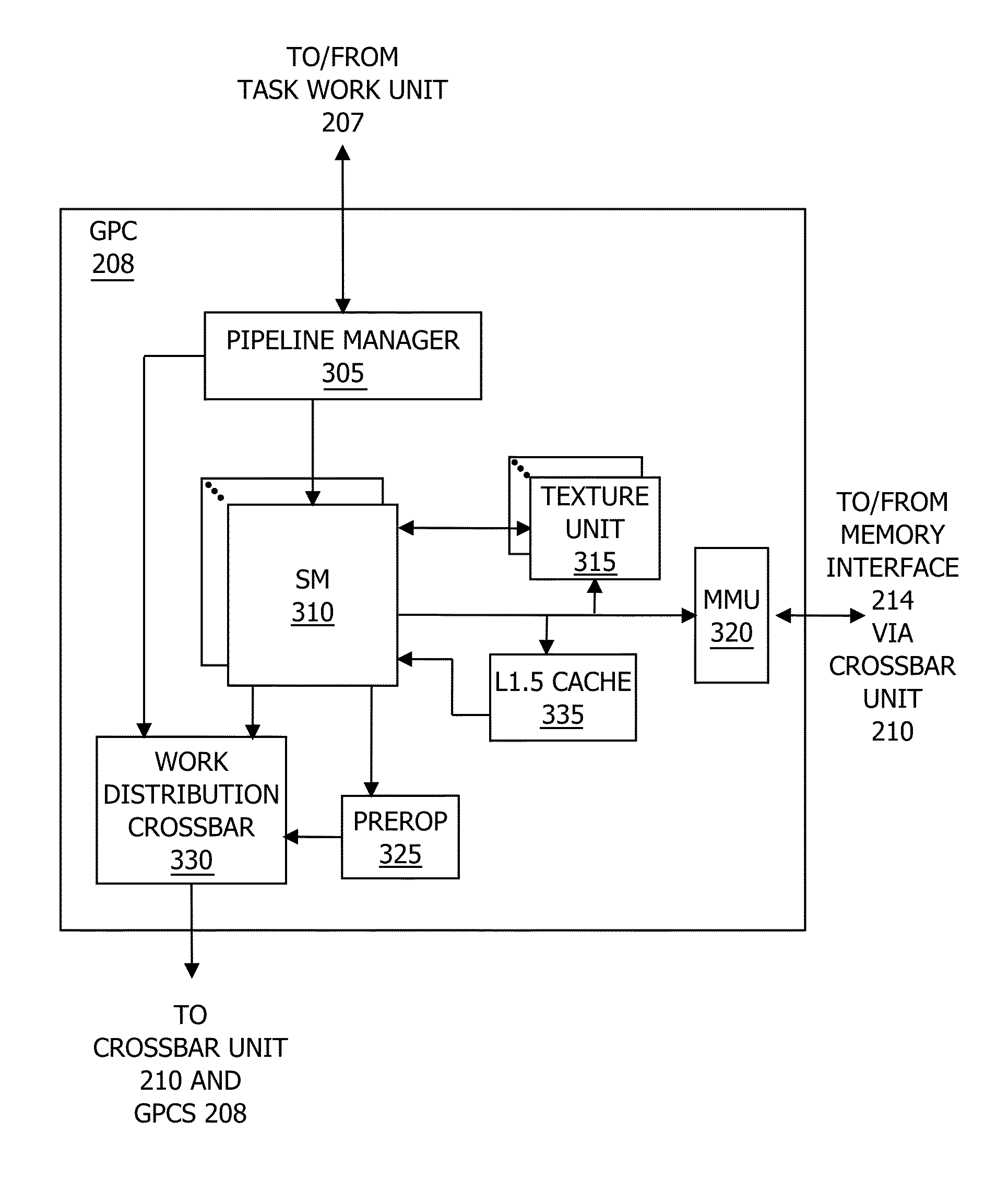
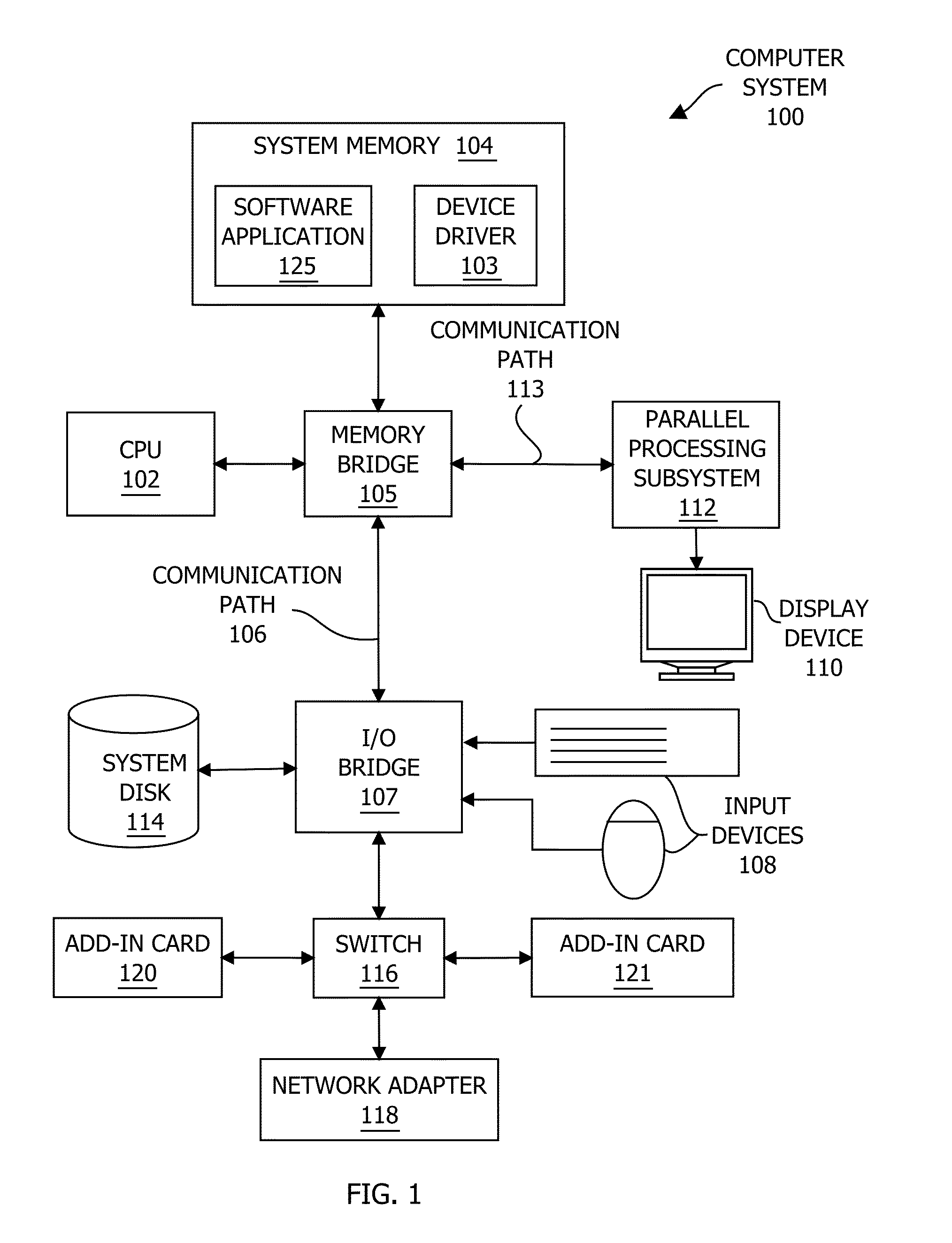
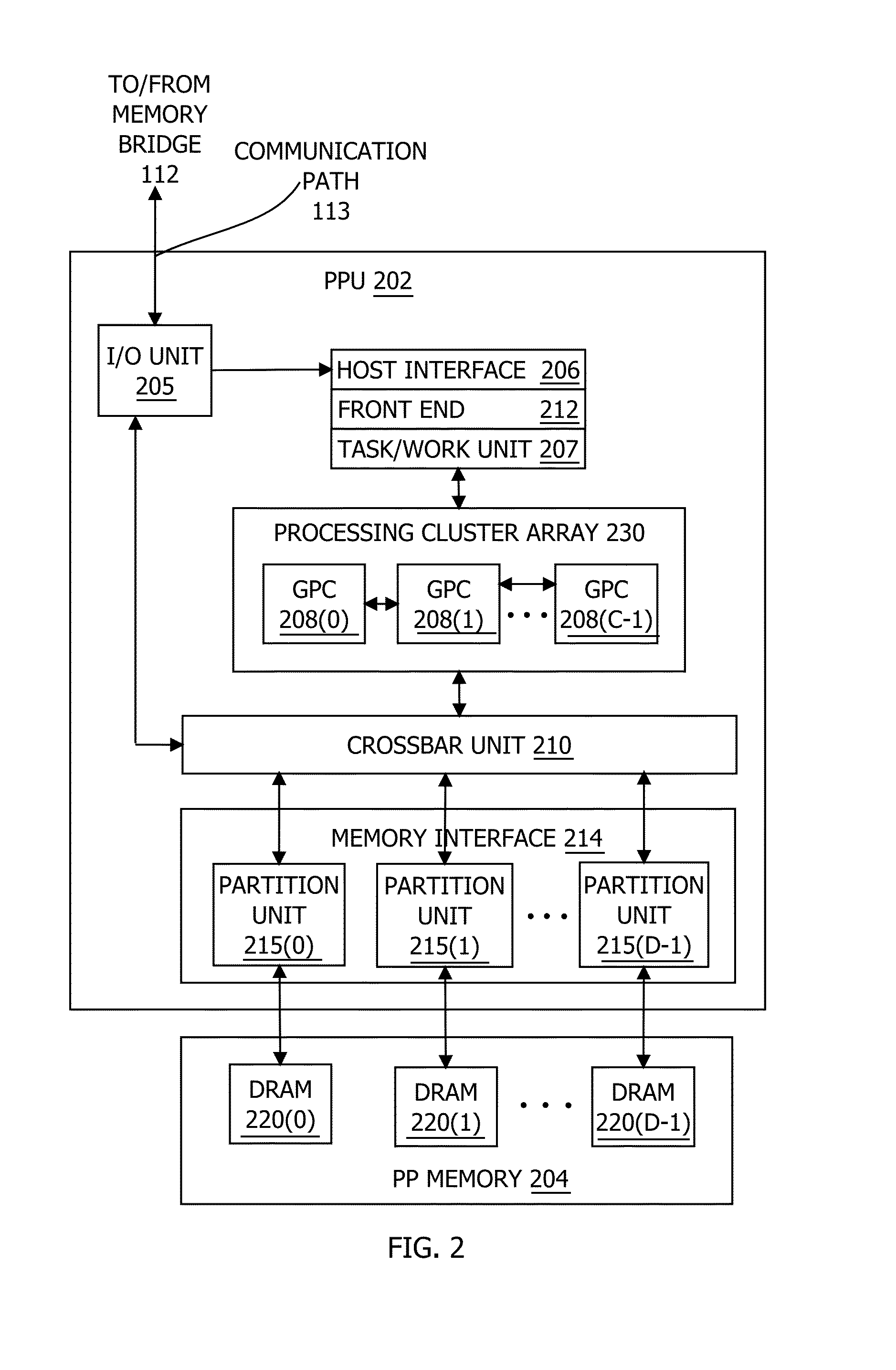
[0019]FIG. 1 is a block diagram illustrating a computer system 100 configured to implement one or more aspects of the present invention. As shown, computer system 100 includes, without limitation, a central processing unit (CPU) 102 and a system memory 104 coupled to a parallel processing subsystem 112 via a memory bridge 105 and a communication path 113. Memory bridge 105 is further coupled to an I / O (input / output) bridge 107 via a communication path 106, and I / O bridge 107 is, in turn, coupled to a switch 116.

[0020]In operation, I / O bridge 107 is configured to receive user input information from input devices 108, such as a keyboard or a mouse, and forward the input information to C...


PUM


Abstract

One embodiment of the present invention includes a parallel processing unit (PPU) that performs pixel shading at variable granularities. For effects that vary at a low frequency across a pixel block, a coarse shading unit performs the associated shading operations on a subset of the pixels in the pixel block. By contrast, for effects that vary at a high frequency across the pixel block, fine shading units perform the associated shading operations on each pixel in the pixel block. Because the PPU implements coarse shading units and fine shading units, the PPU may tune the shading rate per-effect based on the frequency of variation across each pixel group. By contrast, conventional PPUs typically compute all effects per-pixel, performing redundant shading operations for low frequency effects. Consequently, to produce similar image quality, the PPU consumes less power and increases the rendering frame rate compared to a conventional PPU.

Description

BACKGROUND OF THE INVENTION[0001]1. Field of the Invention[0002]Embodiments of the present invention relate generally to graphics processing and, more specifically, to adaptive shading in a graphics processing pipeline.[0003]2. Description of the Related Art[0004]A typical computer system includes a central processing unit (CPU) and a graphics processing unit (GPU). Some GPUs are capable of very high performance using a relatively large number of small, parallel execution threads on dedicated programmable hardware processing units. The specialized design of such GPUs usually allows these GPUs to perform certain tasks, such as rendering 3-D scenes, much faster than a CPU. However, the specialized design of these GPUs also limits the types of tasks that the GPU can perform. By contrast, the CPU is typically a more general-purpose processing unit and therefore can perform most tasks. Consequently, the CPU usually executes the overall structure of a software application and then configu...

Claims


Application Information

Patent Timeline
Patent Type & Authority Applications(United States)
IPC IPC(8): G06T15/80
CPCG06T15/80G06T15/005
Inventor HE, YONGLUM, ERIC B.ENDERTON, ERICMORETON, HENRY PACKARDFATAHALIAN, KAYVON
Owner NVIDIA CORP
Learn More