
Carbon monoxide (CO) microsir sensor system

a microsir sensor and carbon monoxide technology, applied in the direction of material analysis through optical means, measurement devices, instruments, etc., can solve the problems of difficult to detect carbon monoxide accurately (plus or minus 5%), carbon monoxide (co) has no smell, cannot be seen or tasted, and is very toxic, so as to achieve easy automatic

Inactive Publication Date: 2011-06-16
THE QUANTUM GROUP
View PDF6 Cites 8 Cited by
  • Summary
  • Abstract
  • Description
  • Claims
  • Application Information

AI Technical Summary

Benefits of technology

[0009]The present invention eliminates the need for two sensing disks by the new chemical formulations of the chemistry as described in detail below. The chemistry was reformulated using a single micro- or mini-size sensing disk. The invention involves new formulations of sensing chemistry, specially combined and optimized so that only ONE instead of TWO sensing elements is enough to meet the requirement specified under UL 2034. The new single sensing chemistry formulations have been proven to perform better than both the regular-sized SIR sensors in the SIR assembly. The micro-sized porous silica substrates are similar in composition but slightly different in pore diameter and structure. The regular-sized substrates are ˜0.100″ diameterט0.050, 0.100, 0.150, and 230″ thick and the micro-sized substrates are ˜0.100 diameterט0.025″ and 0.050″ thick. The new sensing chemistry formulations can be applied to the substrates by either the injection or the immersion method. The injection method eliminates waste.

Problems solved by technology

These compounds are difficult to detect accurately (plus or minus 5%) without expensive technology such as instruments costing over $100 to $100,000 depending upon the accuracy and type of technology used.
Carbon monoxide (CO) has no smell, cannot be seen or tasted, but is very toxic.
Such gases are hazardous to humans in automobiles, airplanes, mines, residential and commercial buildings, and other environments in which humans live, work or spend time.
While this system is effective in detecting carbon monoxide, it has not met with commercial acceptance due to the short functional life of the catalyst.
However, these formulations, which used only one solid-state substrate does not provide adequate sensitivity under high humidity and high temperature conditions, which cannot resist false alarm limits as specified in the Underwriters Laboratories (UL) 2034.

Method used


Image

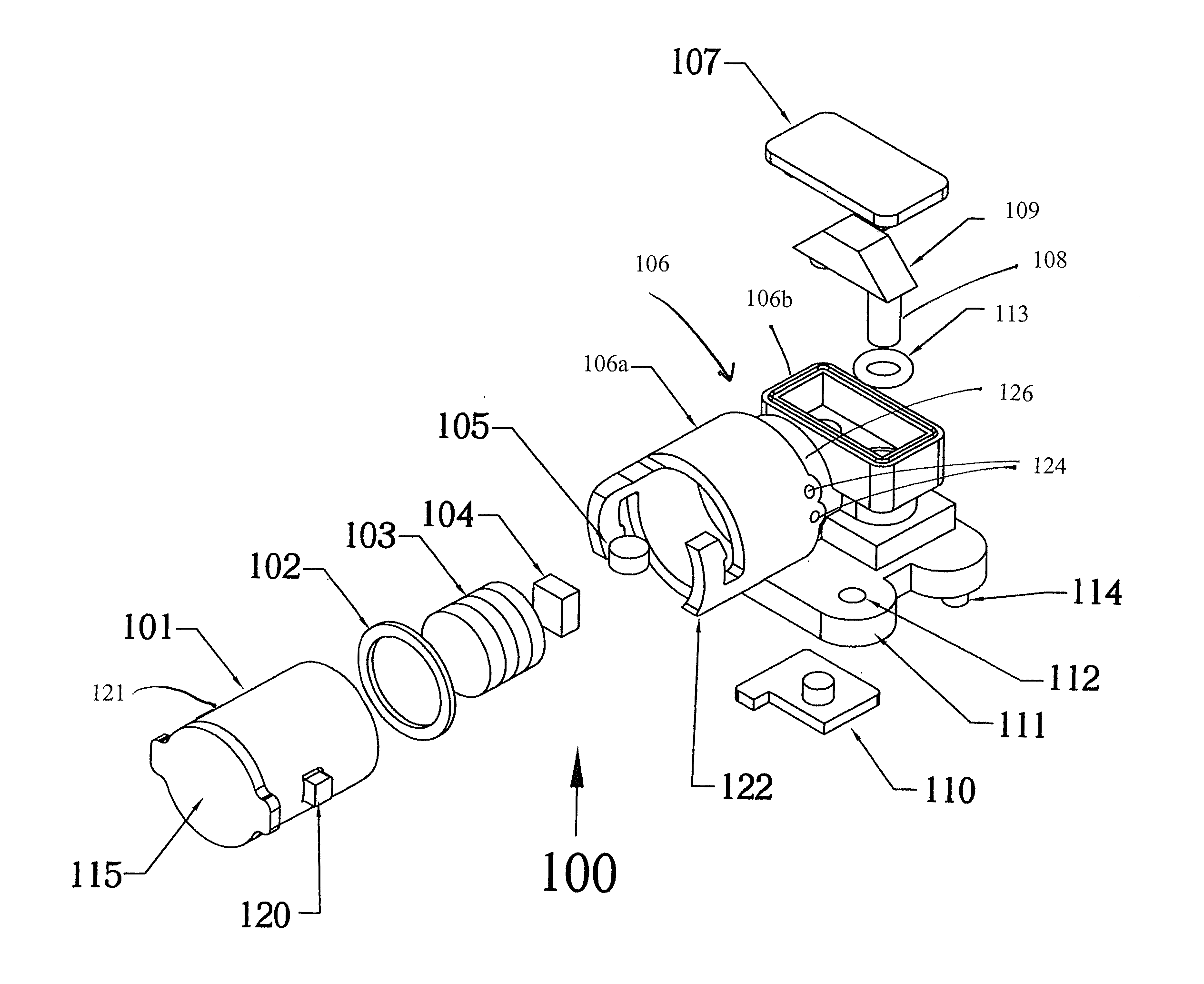
  • Carbon monoxide (CO) microsir sensor system
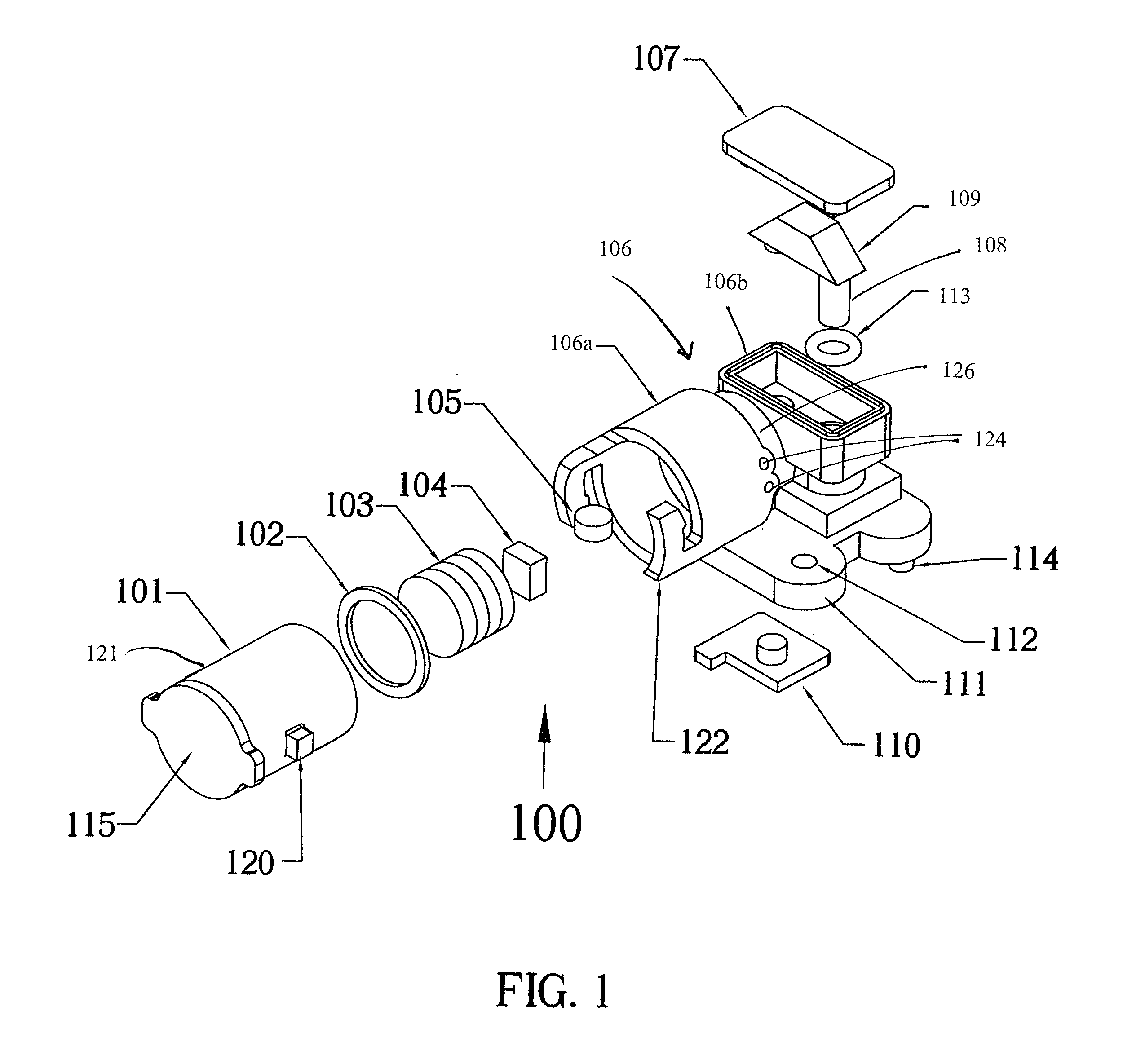
  • Carbon monoxide (CO) microsir sensor system
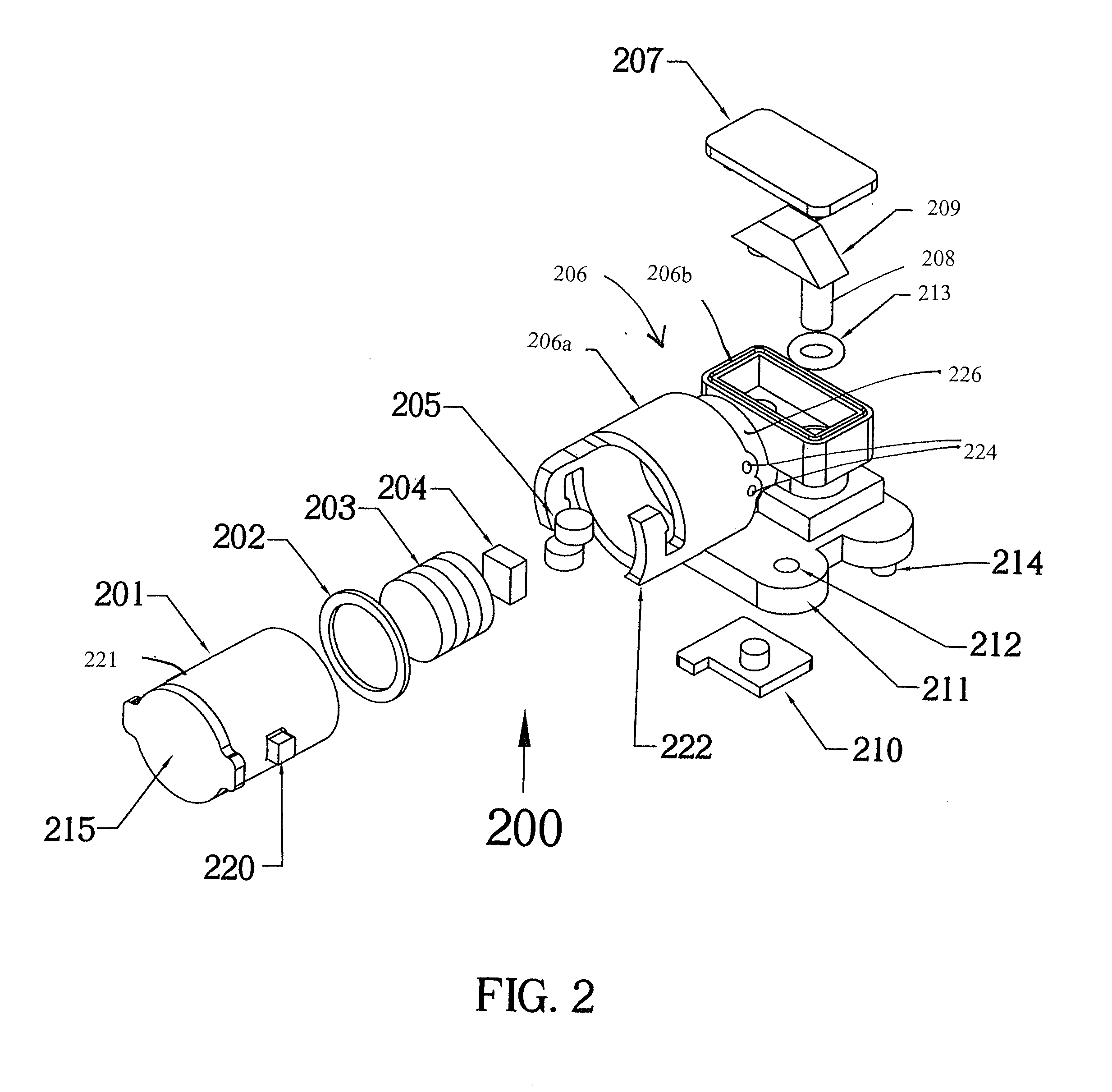
  • Carbon monoxide (CO) microsir sensor system

Examples


embodiment 1

Preferred Embodiment 1

Visual CO Indicator

Example 1A

Single CO Sensing Formulation S6e on Regular-Sized SPS for SIR

[0104]“Soak Method”

[0105]100 of 0.150″ diameter×0.100″ thick silica porous silicate disks with pore diameter ranging from 200 to 300 angstroms and surface area ranging from 100 to 200 square meter per gram are soaked in a 15-mL of the new S6e sensing formulation containing 7.7 mmole of H4SiMo12O40.xH2O, 77.7 mmole of CaCl2.2H2O, 2.7 mmole of CCl3COOH, 0.16 mmole of copper trifluoroacetylacetonate, 1.74 mmole of CuCl2.2H2O, 8.6 mmole of CaBr2.2H2O, 1.126 mmole of Gamma-Cyclodextrin, 0.97 mmole of Hydroxy-Beta-Cyclodextrin, 1.89 mmole of Na2PdCl4, 23.89 mmole of PdCl2, and 0.55 mmole of Beta-Cyclodextrin. After 1 day of soaking, the excess solution is removed and the sensor dried using Kimwipe tissue paper. Sensors are spread flat on a clean Pyrex or plastic tray and allowed to dry slowly inside a polyester felt pillow case inside an humidity and temperature controlled room...

embodiment 2

Preferred Embodiment 2

Single Sensing Element MICROSIR for CO Alarm that Meets UL 2034

example 1b

Single Sensing Formulation S6e on Mini-SPS for MICROSIR

[0109]“Soak Method”

[0110]600 of the mini-sized silica porous silicate disks with pore diameter ranging from 200 to 300 angstroms and surface area ranging from 100 to 200 square meter per gram are soaked in a 15-mL of the new S6e sensing formulation containing 7.7 mmole of H4SiMo12O40.xH2O, 77.7 mmole of CaCl2.2H2O, 2.7 mmole of CCl3COOH, 0.16 mmole of copper trifluoroacetylacetonate, 1.74 mmole of CuCl2.2H2O, 8.6 mmole of CaBr2.2H2O, 1.126 mmole of Gamma-Cyclodextrin, 0.97 mmole of Hydroxy-Beta-Cyclodextrin, 1.89 mmole of Na2PdCl4, 23.89 mmole of PdCl2, and 0.55 mmole of Beta-Cyclodextrin. After 1 day of soaking, the excess solution is removed and the sensor dried using Kimwipe tissue paper. Sensors are spread flat on a clean Pyrex or plastic tray and allowed to dry slowly inside a polyester felt pillow case inside an humidity and temperature controlled room or chamber with relative humidity maintain within 45 to 55% and tempera...


PUM

PropertyMeasurementUnit
pore sizeaaaaaaaaaa
mole ratioaaaaaaaaaa
temperatureaaaaaaaaaa

Abstract

The present invention provides very small low cost apparatus and method for determining the concentration and / or hazard from a target gas by means of optically monitoring one or more sensors that responds to carbon monoxide. The apparatus comprises a photon source optically coupled to the sensor and the photon intensity passing through the sensor is quantified by one or more photodiode(s) in a system, so that the photon flux is a function of at least one sensor's response to the target gas, e.g., transmits light through the sensor to the photodiode. The photocurrent from the photodiode is converted to a sensor reading value proportional to the optical characteristics of the sensors and is loaded into a microprocessor or other logic circuit. In the microprocessor, the sensor readings may be differentiated to determine the rate of change of the sensor readings and the total photons absorbed value may be used to calculate the CO concentration.

Description

CROSS-REFERENCE TO RELATED APPLICATION(S)[0001]This application is a continuation of application Ser. No. 11 / 786,883 filed Apr. 13, 2007, which claimed the benefit of the filing date of U.S. Provisional Application No. 60 / 792,103 filed Apr. 13, 2006, the disclosures of which are incorporated fully herein by reference.FIELD OF THE INVENTION[0002]The present invention relates to improvements for detecting the presence of carbon monoxide by means of one instead of two solid-state sensing elements such as the chemical complexes coated onto porous substrates to produce CO sensors, which was previously described in an earlier invention U.S. Pat. No. 5,618,493, which discloses a means for detecting carbon monoxide sensors, which met UL 2034 but used two sensing elements to do that because one could pass by itself after UL changed the standard in 1995. The single sensor is smaller and less expensive, yet out performs the larger dual sensing system. The single (sensing element) sensor is int...

Claims


Application Information

Patent Timeline
Patent Type & Authority Applications(United States)
IPC IPC(8): G01N33/00
CPCG01N31/22G01N21/783
Inventor GOLDSTEIN, MARK K.OWN, MICHELLE S.
Owner THE QUANTUM GROUP
Learn More