
Backlight unit and liquid crystal display device

a liquid crystal display and backlight technology, applied in lighting device details, lighting and heating apparatuses, instruments, etc., can solve the problems of difficult to make the light enter perpendicularly and affecting the brightness of the liquid crystal display panel

Inactive Publication Date: 2011-06-16
SHARP KK
View PDF4 Cites 119 Cited by
  • Summary
  • Abstract
  • Description
  • Claims
  • Application Information

AI Technical Summary

Benefits of technology

[0031]According to the present invention, it is possible, by use of a diffraction grating formed on the light-exit face of a light guide plate and a refractive optical element formed on the bottom face of the light guide plate, to make high-quality white light exit perpendicularly to the light-exit face.

Problems solved by technology

The reason is that if too much light shines obliquely into the liquid crystal display panel, diminished or uneven brightness may result.
In this case, inconveniently, it is difficult to make the light exit perpendicularly to the top face.
Accordingly, it is difficult to make the light enter perpendicularly the liquid crystal display panel, which is disposed to cover the top face.
This degrades the display quality on the liquid crystal display panel that receives that light.

Method used


Image

  • Backlight unit and liquid crystal display device
  • Backlight unit and liquid crystal display device
  • Backlight unit and liquid crystal display device

Examples


embodiment 1

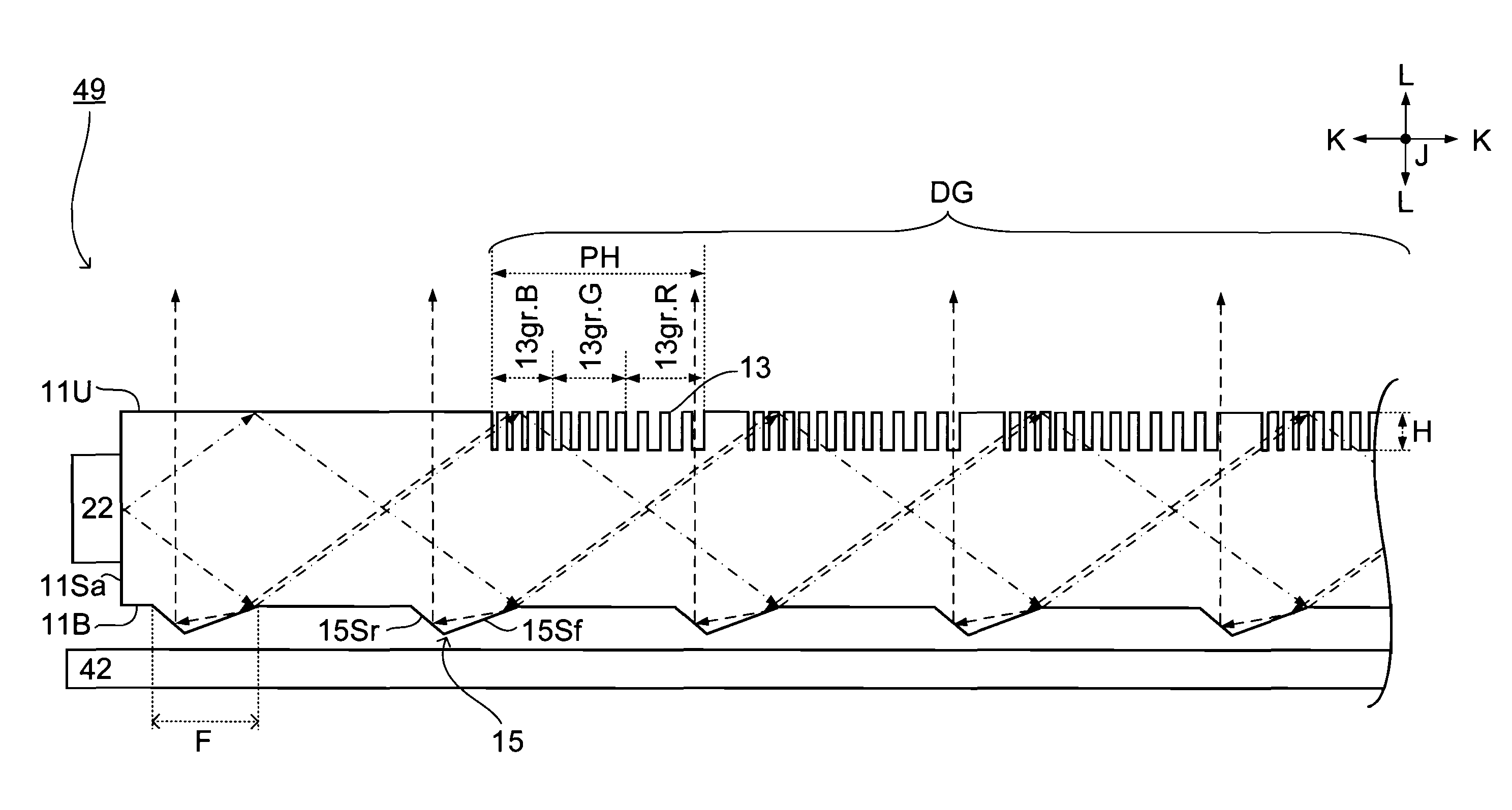
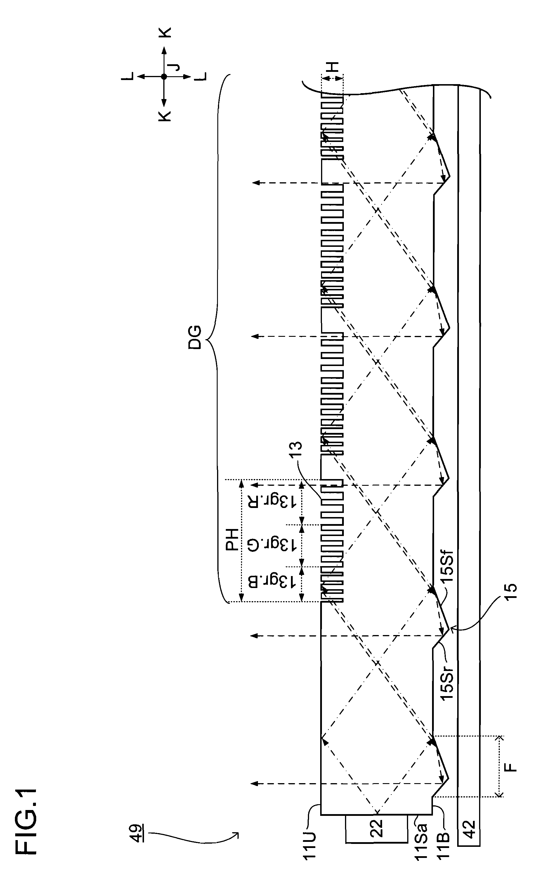
[0046]An embodiment of the present invention will be described below with reference to the accompanying drawings. For convenience' sake, hatching, reference signs, etc. do not necessarily appear in all relevant drawings, in which case reference is to be made to those drawings in which they appear. A solid black dot in a drawing indicates the direction perpendicular to the plane of the paper.

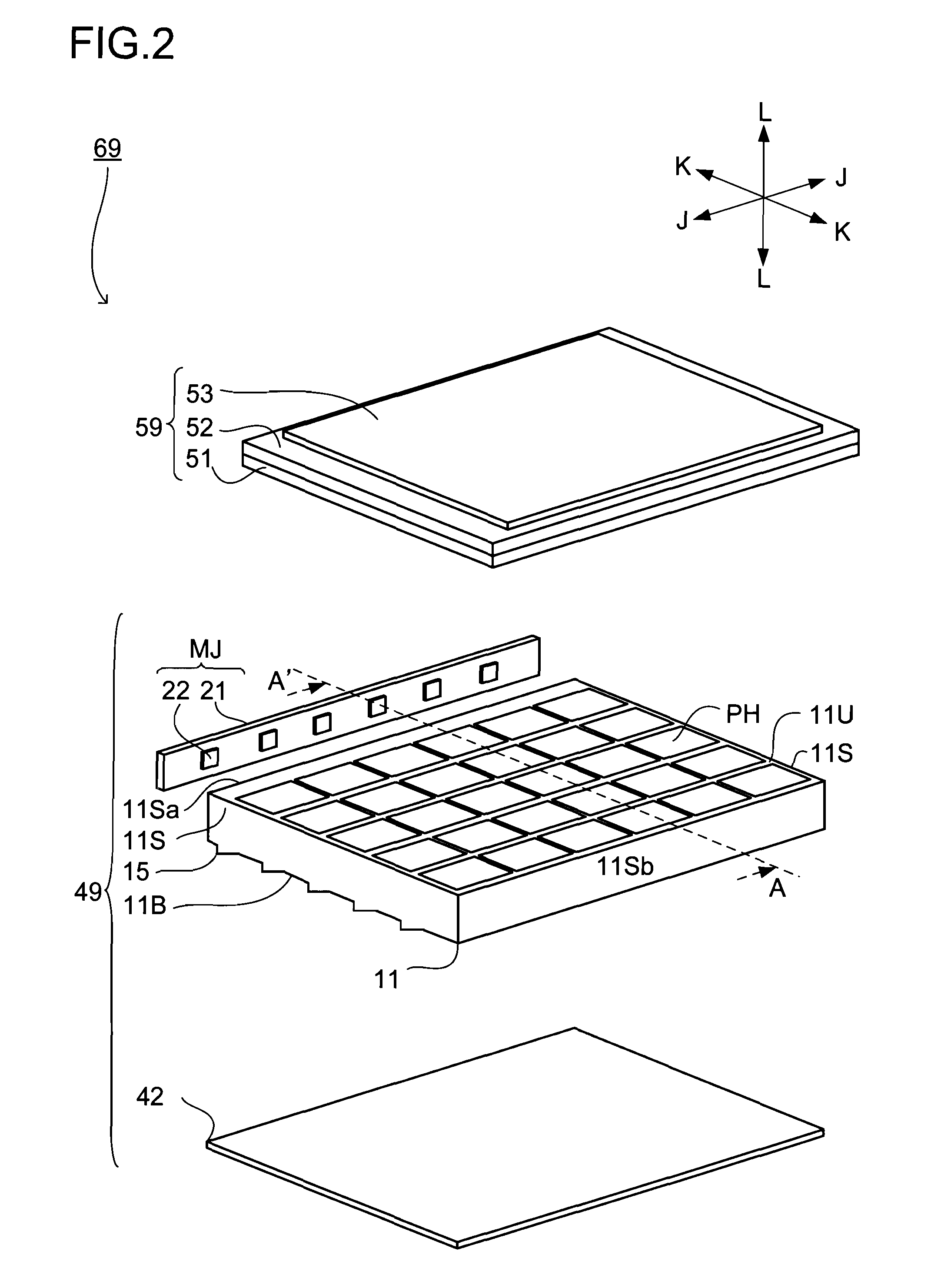
[0047]FIG. 2 is an exploded perspective view of a liquid crystal display device 69. As shown there, the liquid crystal display device 69 comprises a liquid crystal display panel 59 and a backlight unit 49.

[0048]The liquid crystal display panel 59 is composed of an active matrix substrate 51, which includes switching elements such as TFTs (thin-film transistors), and a counter substrate 52, which faces the active matrix substrate 51, stuck together by a sealing member (not shown). The gap between the two substrates 51 and 52 is filled with liquid crystal (not shown). (The active matrix substrate 5...


PUM

PropertyMeasurementUnit
heightaaaaaaaaaa
heightaaaaaaaaaa
wavelength bandsaaaaaaaaaa

Abstract

Three grating piece groups (13gr.Gr.B, 13G, 13R) on the top surface (11U) of a light guide plate correspond to light of different wavelength regions, and respectively diffract and reflect light of the corresponding wavelength region, which is incident thereon at an incident angle within a specific range, back to the incoming direction of the light. The bottom surface (11B) of the light guide plate (11) is provided with a prism (15) for reflecting the backwardly diffracted and reflected light toward the top surface (11U).

Description

TECHNICAL FIELD[0001]The present invention relates to a backlight unit that supplies light to a liquid crystal display panel or the like, and also relates to a liquid crystal display device that incorporates such a backlight unit.BACKGROUND ART[0002]Conventionally, liquid crystal display devices incorporating a non-luminous liquid crystal display panel also incorporate a backlight unit that supplies light to the liquid crystal display panel. Such a backlight unit is expected to shine light as perpendicularly as possible into the liquid crystal display panel. The reason is that if too much light shines obliquely into the liquid crystal display panel, diminished or uneven brightness may result.[0003]Typically, light from a light source is introduced into a single, plate-shaped light guide plate through an edge face thereof so that the light undergoes multiple reflection inside so as to eventually exit from the light guide plate through a top face thereof. In this case, inconveniently,...

Claims


Application Information

Patent Timeline
Patent Type & Authority Applications(United States)
IPC IPC(8): G02F1/13357F21V7/22
CPCG02B6/0036G02F1/133615G02B6/0068G02B6/0038
Inventor YASHIRO, YUJI
Owner SHARP KK
Learn More