
Drill template with integral vacuum attach having plugs

a vacuum attaching and drilling template technology, applied in drilling/boring measurement devices, manufacturing tools, transportation and packaging, etc., can solve the problems of laborious cleanup, lost suction, and high cost of drilling, and achieve the effect of reducing foreign object debris (fod) and enhancing negative pressur

Inactive Publication Date: 2011-06-09
THE BOEING CO
View PDF11 Cites 15 Cited by
  • Summary
  • Abstract
  • Description
  • Claims
  • Application Information

AI Technical Summary

Benefits of technology

[0005]In one aspect, a method of reducing foreign object debris (FOD) during drilling operations is provided. The method includes disposing a vacuum housing with a computer aided design (CAD) formed drill template in an operative position on a work piece, actuating a vacuum operatively connected to the vacuum housing, thereby creating negative pressure between the template and the work piece, the negative pressure acting on the debris resulting from the drilling operations, and enhancing the negative pressure without manipulating the vacuum.
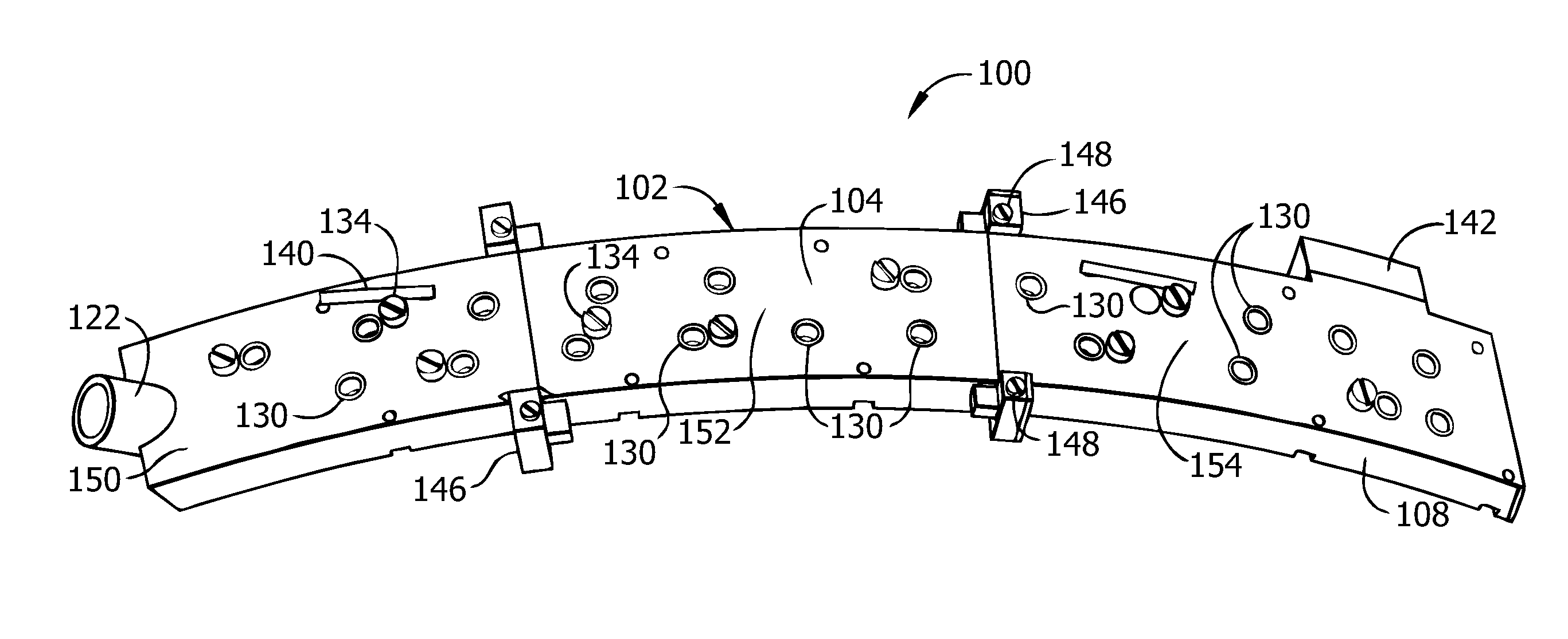
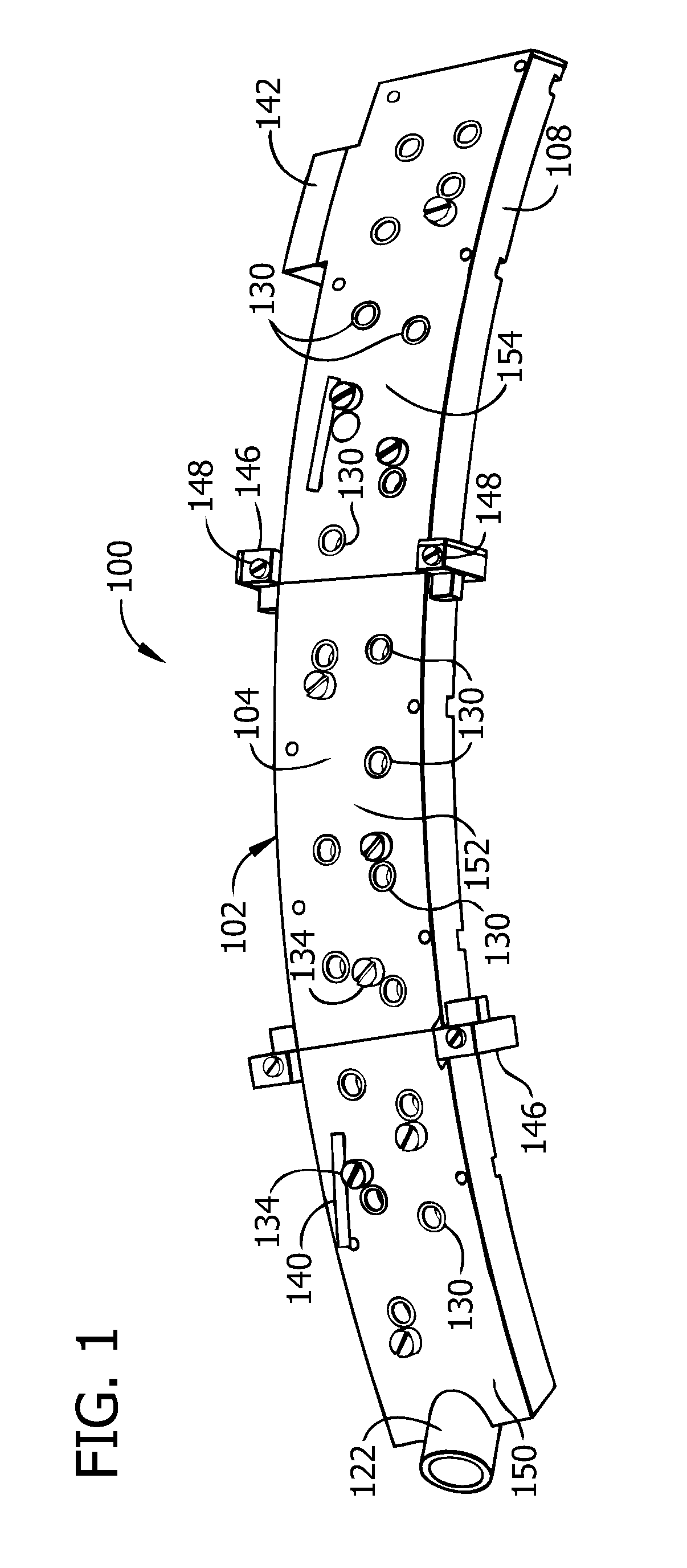
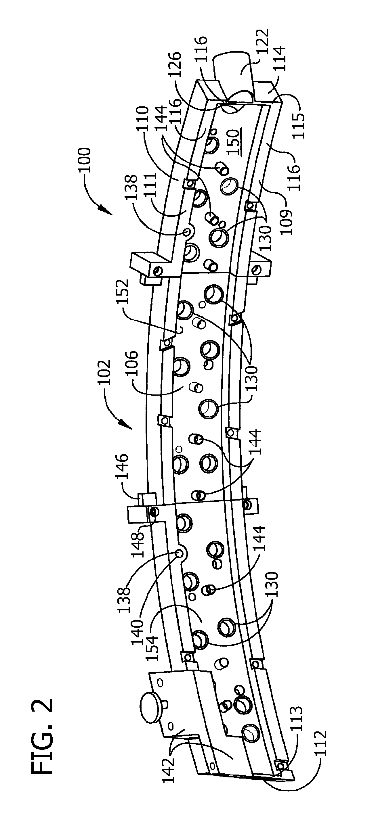
[0006]In another aspect, a drill template for placement adjacent a structure is provided. The drill template includes a vacuum housing comprising a structure contact surface defined to fit adjacent a mold line surface of the structure, a vacuum port extending from the vacuum housing, a plurality of drill bushings extending through the vacuum housing from an outer surface to an inner surface of the vacuum housing, the drill bushings in fluid communication with the vacuum port, and at least one drill bushing plug operable for insertion into one of the drill bushings. The drill bushing plugs are operable for preventing ingress or egress of fluid or debris through the drill bushing into which the drill bushing plug is inserted and further operable for increasing a draw through another of the drill bushings when a vacuum is attached to the vacuum port. The vacuum housing, the vacuum port, the drill bushings, and the at least one drill bushing plug are concurrently fabricated using an additive manufacturing process.

Problems solved by technology

If the templates do include a vacuum system, there often is a loss in suction due to the open holes that allow for drilling.
Additionally, cleanup of the drilling often is labor intensive as well as time intensive as water and particles that may have not been captured by the vacuum could escape through the currently unused drill holes in the template.

Method used


Image

  • Drill template with integral vacuum attach having plugs
  • Drill template with integral vacuum attach having plugs
  • Drill template with integral vacuum attach having plugs

Examples


Embodiment Construction

[0013]The following detailed description is of the best currently contemplated mode of carrying out the invention. The description is not to be taken in a limiting sense, but is made merely for the purpose of illustrating the general principles of the invention, since the scope of the invention is best defined by the appended claims.

[0014]Broadly, one embodiment of the present invention provides a template for precisely drilling a pattern of holes in a structure and for collecting debris generated by the drilling process including plugs for insertion into holes that are not being used during specific portions of the drilling process. The structure may be part of a product manufactured in the aerospace, marine, or refrigeration industries as typified by, for example, a skin portion attached to a frame substructure. Drill templates are generally useful in such situations for drilling holes in precise locations through the skin and into or through a portion of the frame, for example, f...


PUM

PropertyMeasurementUnit
pressureaaaaaaaaaa
anglesaaaaaaaaaa
heataaaaaaaaaa

Abstract

A method of reducing foreign object debris (FOD) during drilling operations is provided. The method includes disposing a vacuum housing with a computer aided design (CAD) formed drill template in an operative position on a work piece, actuating a vacuum operatively connected to the vacuum housing, thereby creating negative pressure between the template and the work piece, the negative pressure acting on the debris resulting from the drilling operations, and enhancing the negative pressure without manipulating the vacuum.

Description

BACKGROUND[0001]The present disclosure generally relates to manufacture and assembly of structures and, more particularly, to drilling holes into a part at precise locations and angles. The disclosure further relates to the collecting of debris, for example, as generated when drilling into a composite or metallic aircraft part. Such debris includes one or more of composite dust, metallic drill chips, water, and any other lubricating or cooling fluids generated by the drilling process.[0002]In conventional practice, before a pattern of holes is drilled in a part to be assembled into a structure, a template, or jig, is made and placed on the surface of the part to be drilled. For example, in the aerospace industry, the structure, or assembly, may be a composite aircraft skin over an aluminum substructure. Examples may also be found in the marine and refrigeration industries, such as applications to boat hulls and heating / air conditioning ducts. The template or jig contains holes confo...

Claims


Application Information

Patent Timeline
Patent Type & Authority Applications(United States)
IPC IPC(8): B23B47/28B23B35/00B23B47/34
CPCB23B47/28B23B49/026B23B2215/04Y10T408/50Y10T408/44Y10T408/554Y10T408/03B23Q11/0046B23B47/287B23B47/34
Inventor INMAN, JOHN E.DIETRICH, DAVID MICHAELMACKE, JR., JOHN G.HAYES, MICHAEL W.
Owner THE BOEING CO
Learn More