
Substrate treatment process

a technology of substrate treatment and spray system, which is applied in the direction of cleaning process and equipment, chemistry apparatus and processes, etc. it can solve the problems of fire hazards, inability to achieve adequate adhesion to polymeric (organic), ceramic, glass and metallic (inorganic) adherends, and repeated and difficult problems, so as to improve adhesion, wettability or coatability, and improve the effect of adhesion

Inactive Publication Date: 2011-06-09
HITACHI HIGH-TECH CORP
View PDF23 Cites 5 Cited by
  • Summary
  • Abstract
  • Description
  • Claims
  • Application Information

AI Technical Summary

Benefits of technology

This system provides a single-step process for preparing substrates for bonding, coating, and curing, achieving higher surface free energy and cleanliness without the need for vacuum environments or hazardous chemicals, suitable for various substrates and industrial applications.

Problems solved by technology

Achieving adequate adhesion to polymeric (organic), ceramic, glass and metallic (inorganic) adherends is a recurring and difficult problem throughout many industries.
Often what works for one specific application will not be effective for another, thus specific treatments need to be developed for each.
For example, flame surface treatments present fire hazards and may damage heat-sensitive substrates.
Solvent cleaning employing hazardous organic solvents such as acetone, toluene and methyl ethyl ketone (MEK) and acid or alkaline etching solutions present flammability, operator safety and / or ecological hazards, or may damage the substrate.
Mechanical abrasion creates a particle aid residue clean-up issue and may damage critical surface topography.
However, this requires performing a cleaning step independent of and prior to surface treatment.
For example, solvent cleaning is acceptable for cleaning most substrates free of organic contaminants but has limited utility where a distinct change in the chemical nature of the substrate surface is required.
Although, mechanical abrasion will remove hardened surface layers such as old polymeric coatings, paint, adhesives and metal oxides, it may not necessarily adequately treat the underlying exposed substrate surface.
The main drawbacks with this invention as it relates to surface cleaning and treatment is that it must be performed within a vacuum environment, necessitating the use of expensive vacuum chambers, pumps and environmental controls.

Method used


Image

  • Substrate treatment process
  • Substrate treatment process
  • Substrate treatment process

Examples


Embodiment Construction

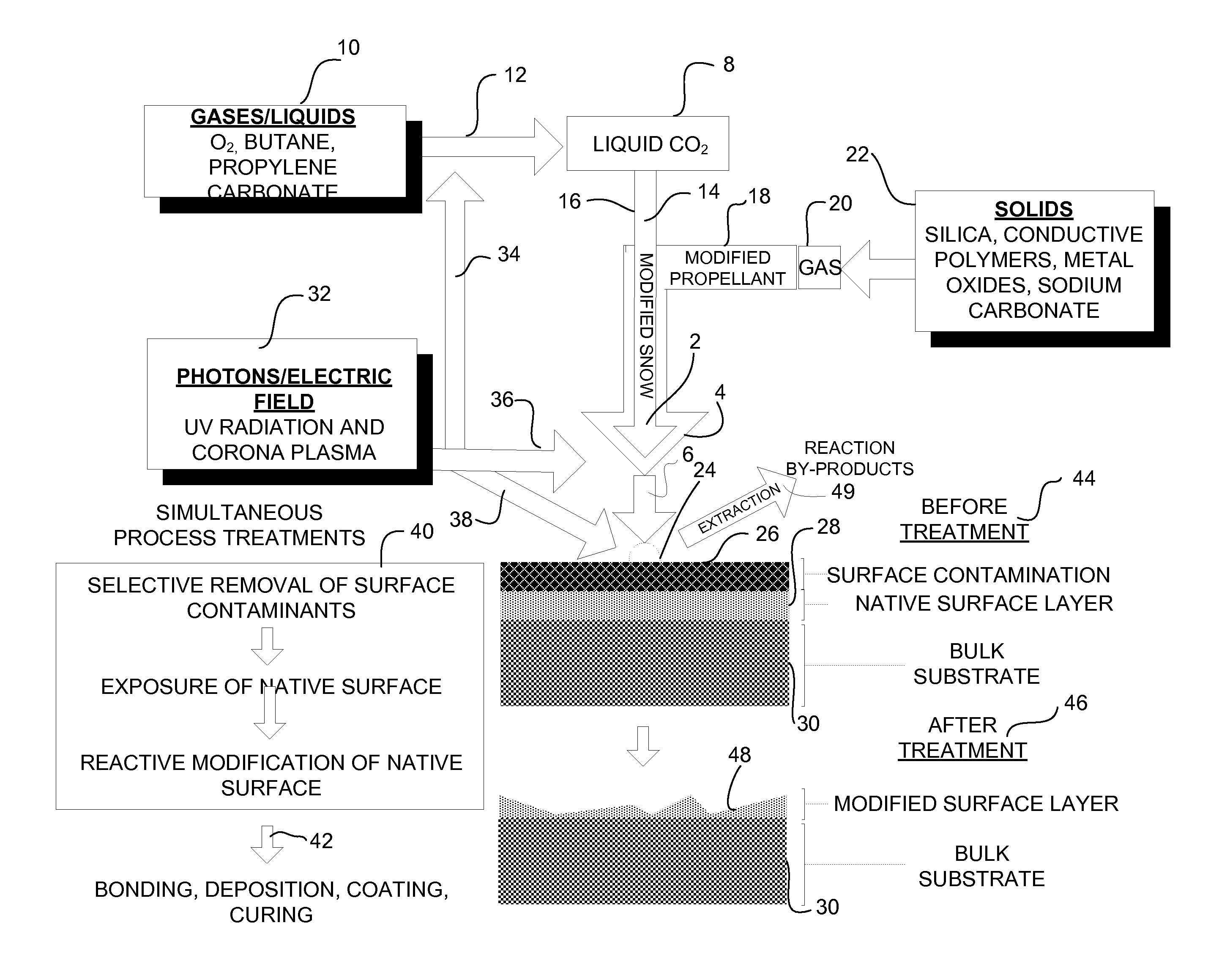
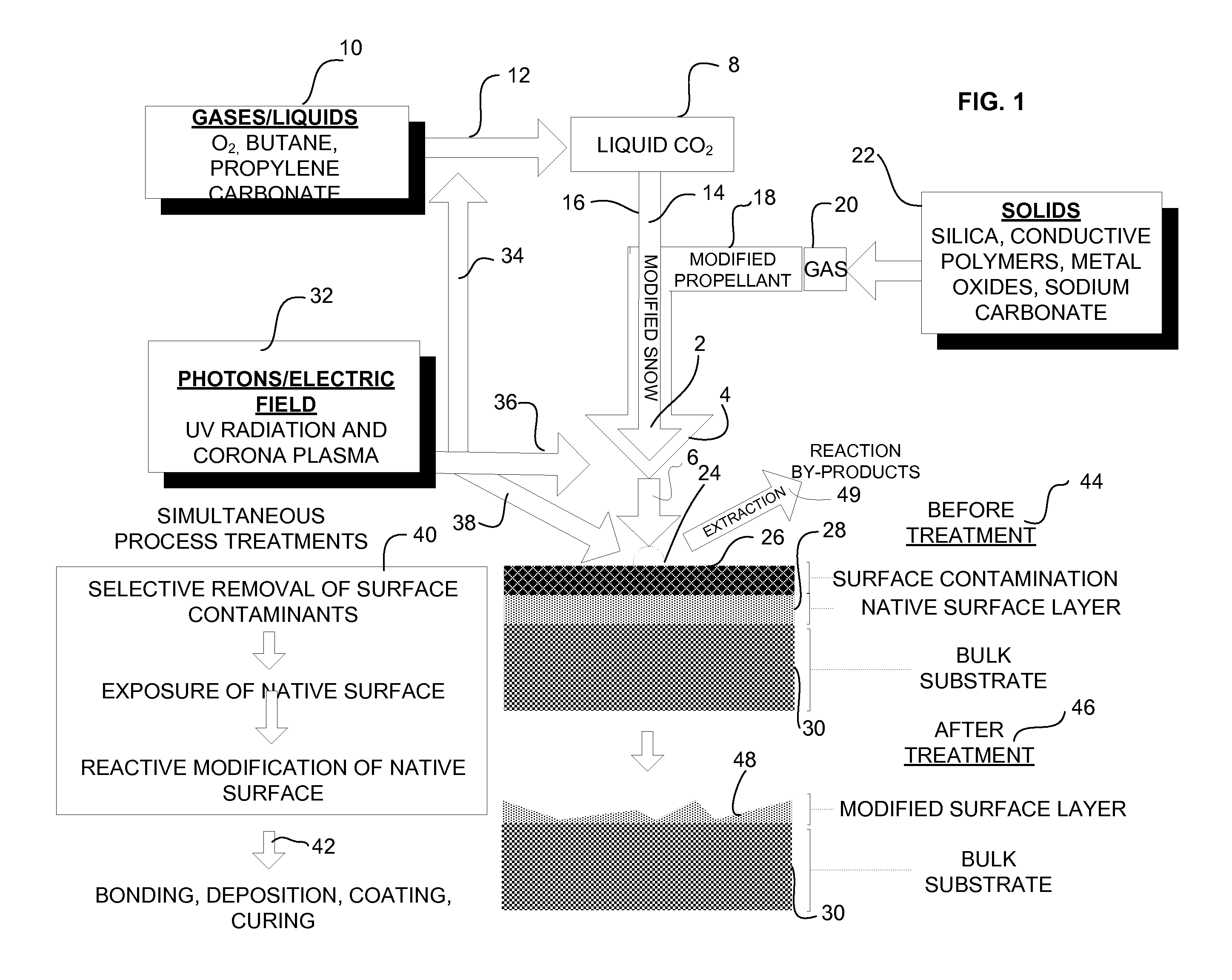
Turning now to a more detailed consideration of the preferred embodiments of the present invention, FIG. 1 illustrates a schematic diagram of the exemplary dense fluid spray surface cleaning and modification process. Referring to FIG. 1, the present invention employs three cleaning and modification streams including a modified solid carbon dioxide (snow) spray stream 2, a modified snow propellant (TIG—thermal inert gas) stream 4 and / or a modified TIG-Snow dense fluid cleaning and modification spray stream 6.

A modified snow spray stream 2 is generated as follows. Using a source of liquid carbon dioxide 8 which is physicochemically modified with various organic and / or inorganic gases or liquids 10, and mixtures thereof, including but not limited to, oxygen gas, n-butane gas, propylene carbonate liquid via injection 12 of said modifiers into said liquid carbon dioxide 8. Following this, the liquid carbon dioxide is condensed into a solid using an enhanced condensation process 14 develo...


PUM

PropertyMeasurementUnit
voltageaaaaaaaaaa
energyaaaaaaaaaa
energyaaaaaaaaaa

Abstract

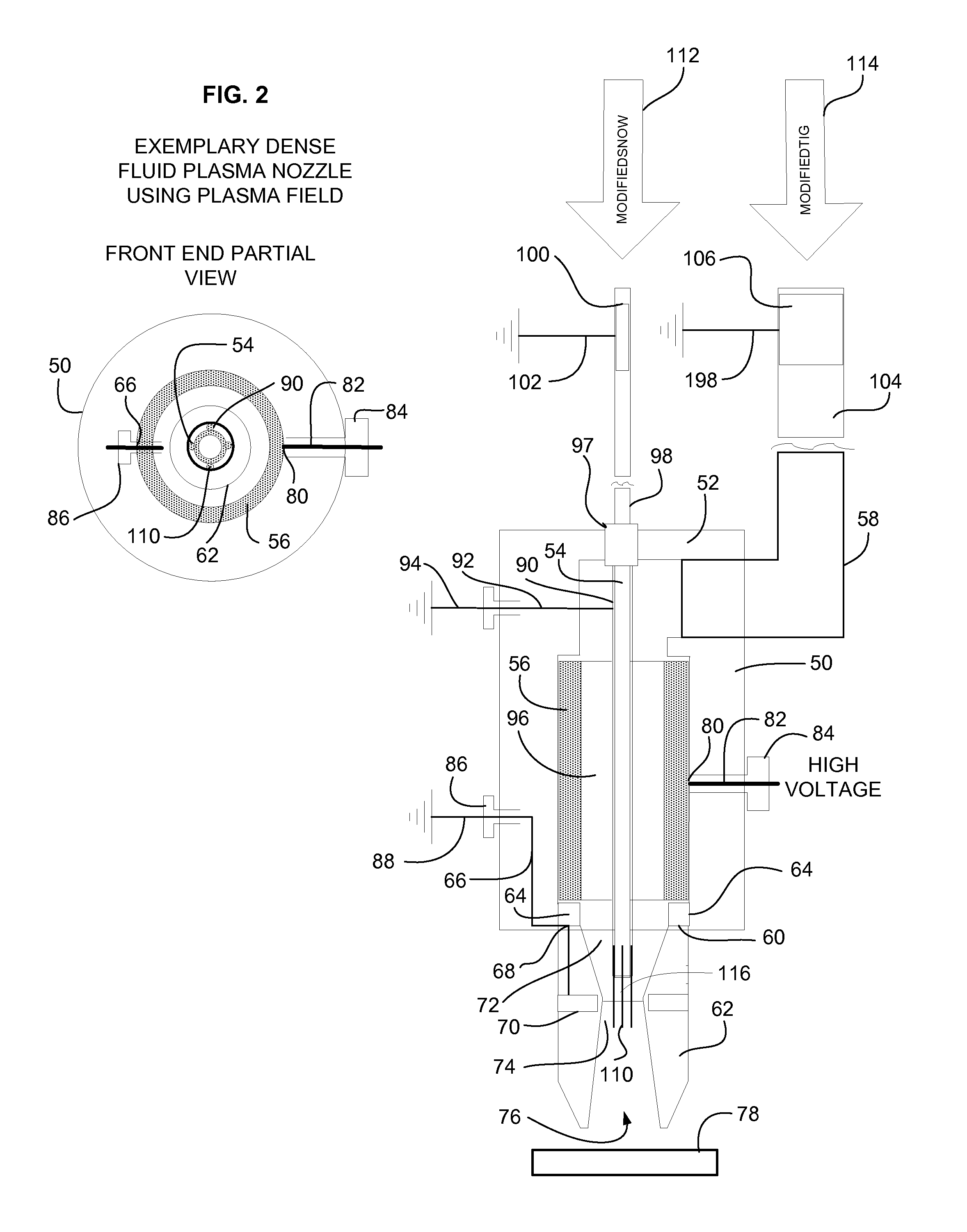
A method of forming a plasma to physicochemically modify properties of a fluid spray in a substrate treatment processes includes providing an applicator in proximity to the substrate. The applicator comprises an electrically insulated main body portion containing a cavity, a tube axially positioned within the cavity for transporting a first fluid, an annular electric-field generator positioned within the cavity between the main body portion and the tube, a region between the tube and the generator for transporting a second fluid, and a nozzle connected to the main body portion for mixing the first fluid with the second fluid to form the fluid spray. The tube, the nozzle or the substrate are selectively grounded. Upon activating the electric-field generator, plasma is formed within the tube or about the region between the tube and the generator when the tube is grounded, within the nozzle when the nozzle is grounded or between the nozzle and the substrate when the substrate is grounded.

Description

BACKGROUND OF INVENTIONThe present invention relates in general to a cleaning spray system which employs a solid carbon dioxide (snow) spray mixture stream, physicochemically modified to contain reactive inorganic gaseous species, which is directed at variable velocity, spray temperatures, and pressures onto substrate surfaces of components or articles that require cleaning and substrate treatment to allow for better bonding, gluing, markability, paintability, coatability or pottability. Various embodiments are incorporated herein which enhance the utility of the present invention.The joining or bonding of substrates is a surface phenomenon, therefore surface preparation prior to bonding is critical for successful bonding. The sole purpose of surface preparation is to attain adherend surfaces receptive to the development of strong, durable bonded joints. It is desirable to have the basic adherend material (clean native substrate surface) exposed directly to the bonding agent (i.e., ...

Claims


Application Information

Patent Timeline
Patent Type & Authority Applications(United States)
IPC IPC(8): B08B7/00B24C1/00
CPCB08B7/0021B08B7/0035B08B7/0057B24C1/086B08B7/02B24C1/003B08B7/0092
Inventor JACKSON, DAVID P.
Owner HITACHI HIGH-TECH CORP
Learn More