
Method of controlling adaptive headlamp

Inactive Publication Date: 2011-06-02
HYUNDAI MOTOR CO LTD +1
View PDF5 Cites 4 Cited by
  • Summary
  • Abstract
  • Description
  • Claims
  • Application Information

AI Technical Summary

Benefits of technology

[0014]Various aspects of the present invention are directed to provide a method of controlling an adaptive head lamp which can simplify a closed loop control system and eliminate a feedback sensor.
[0021]With the configuration of the method of controlling the adaptive head lamp, the control system is simplified by employing an open loop control system instead of a complicated closed-loop system, and the motor is driven in a micro stepping manner to secure the confidence. When the driving unit is positioned at a mechanical stopper which is in a stall state, the position of the head lamp can be verified by the method of detecting a counter electromotive force, thereby eliminating a separate sensor mounting.

Problems solved by technology

When the vehicle turns to the right or left or accelerates, it is difficult for a driver to secure the field of vision only by the fixed head lamp.
However, in a case in which the head lamp is wrongly controlled, it may lead to a car accident.
Therefore, the confidence in a rotational error comes to the fore as an important problem.
However, in the case of employing the control system, since a closed loop with a feedback sensor is added, the control is complicated and the cost is increased, in comparison with an open loop control system.
Further, in a case of mounting the feedback sensor on the actuator, it occupies a space, which lowers the degree of freedom in designing.
In addition, an error in the operation is determined depending upon the mounting accuracy of the feedback sensor, and it is possible to correct the error by the feedback control.

Method used


Image

  • Method of controlling adaptive headlamp
  • Method of controlling adaptive headlamp
  • Method of controlling adaptive headlamp

Examples


Embodiment Construction

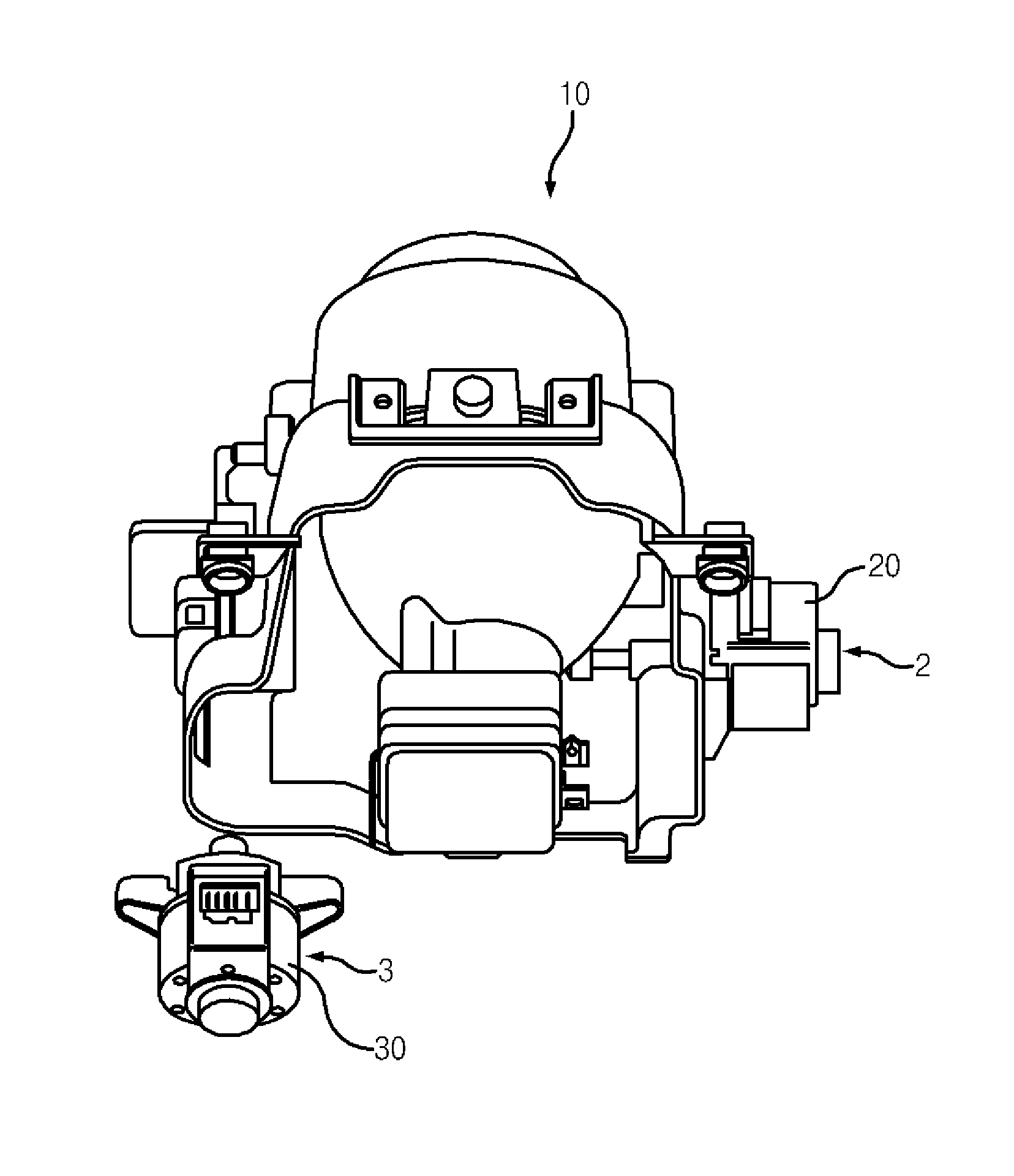
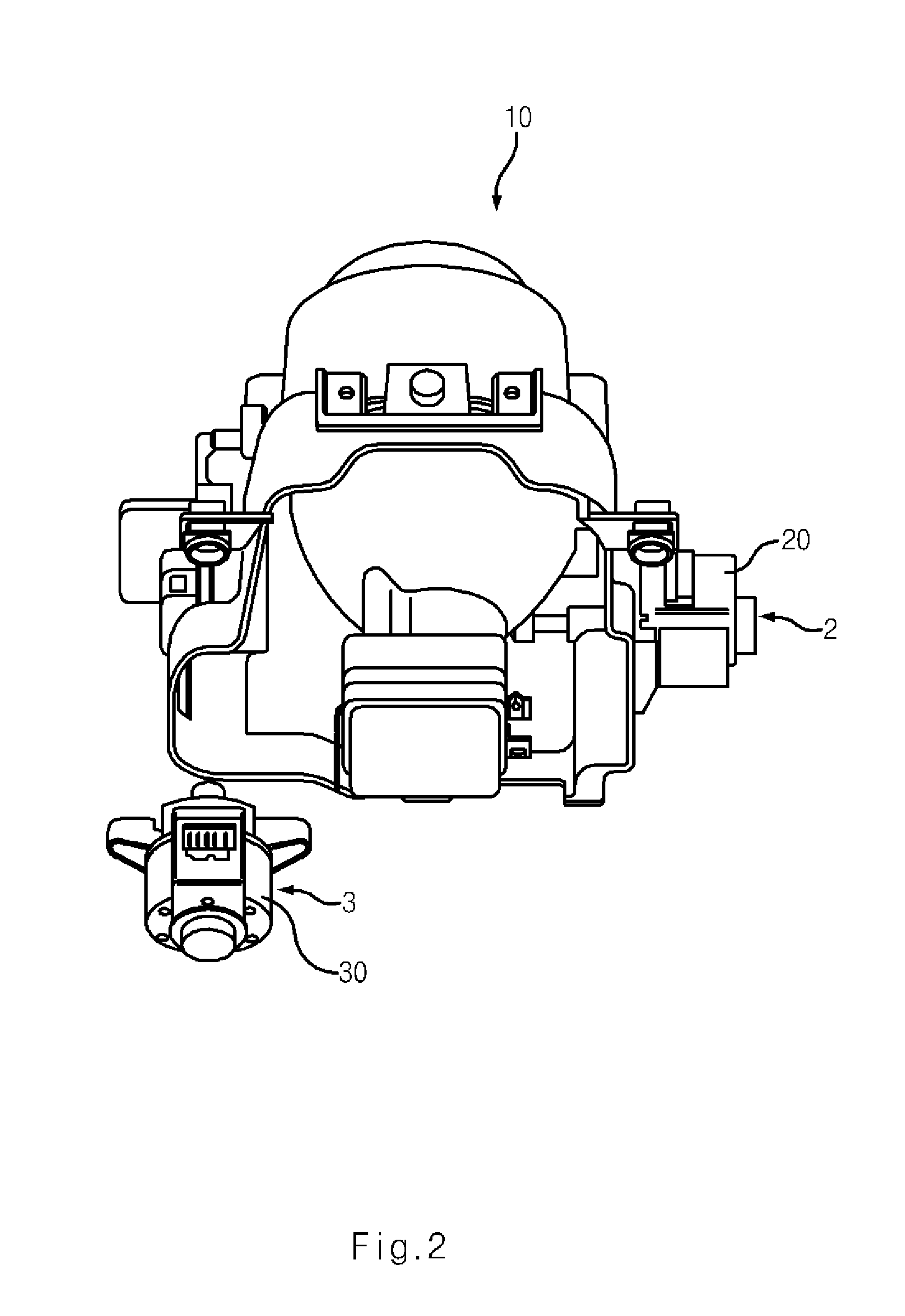
[0028]Reference will now be made in detail to various embodiments of the present invention(s), examples of which are illustrated in the accompanying drawings and described below. While the invention(s) will be described in conjunction with exemplary embodiments, it will be understood that present description is not intended to limit the invention(s) to those exemplary embodiments. On the contrary, the invention(s) is / are intended to cover not only the exemplary embodiments, but also various alternatives, modifications, equivalents and other embodiments, which may be included within the spirit and scope of the invention as defined by the appended claims.

[0029]The configuration of an adaptive head lamp and a control method thereof according to an exemplary embodiment of the present invention will now be described in detail with reference to the accompanying drawings.

[0030]The adaptive head lamp according to an exemplary embodiment of the present invention includes a head lamp 10 which...


PUM


Abstract

A method of controlling an adaptive head lamp including a control unit for detecting a driving signal of a vehicle to control an actuator which controls the head lamp in a horizontal or vertical direction in accordance with a control signal of the control unit, may include steps of, a) verifying whether an ignition of the vehicle is turned on or off, b) after the ignition of the vehicle is verified, driving the actuator to move the head lamp to a rightmost or leftmost position in the horizontal direction, or a lowermost or uppermost position in the vertical direction, c) driving the actuator by a predetermined number of pulses previously set in a micro stepping manner in a direction opposite to a driving direction of the headlamp at the step b), and d) setting a position of the head lamp determined at the step c) as an initial position.

Description

CROSS-REFERENCE TO RELATED APPLICATION[0001]The present application claims priority to Korean Patent Application No. 10-2009-117986, filed on Dec. 1, 2009, the entire contents of which is incorporated herein for all purposes by this reference.BACKGROUND OF THE INVENTION[0002]1. Field of the Invention[0003]The present invention relates to a method of controlling an adaptive head lamp, and more particularly, to a method of controlling an adaptive head lamp which can simplify a closed loop control system and eliminate a feedback sensor.[0004]2. Description of Prior Art[0005]A conventional head lamp 1 shown in FIG. 1 irradiates light only in a fixed direction toward the front of a vehicle, with the head lamp fixed to the vehicle.[0006]When the vehicle turns to the right or left or accelerates, it is difficult for a driver to secure the field of vision only by the fixed head lamp.[0007]An adaptive head lamp has been proposed which can rotate the head lamp by using actuators to adjust hor...

Claims


Application Information

Patent Timeline
IPC IPC(8): B60Q1/04
CPCB60Q2200/38B60Q1/076B60Q1/08B60Q11/00
Inventor CHOI, SUNG UKKIM, HUN SOOJEONG, HEE JUNOH, SE WOOKLEE, HYUN-SOO
Owner HYUNDAI MOTOR CO LTD
Learn More