
Multiple Frequency Energy Supply and Coagulation System

a multi-frequency energy supply and coagulation system technology, applied in the field of heat treatment of living body tissue, can solve the problems of reducing the amount of systemic chemotherapy reaching the tumor, reducing the efficiency of systemic chemotherapy, and affecting the efficiency of coagulation, so as to achieve the effect of high input vs, lower efficiency, and high power efficiency of the system

Inactive Publication Date: 2011-05-26
ENDOCARE
View PDF99 Cites 26 Cited by
  • Summary
  • Abstract
  • Description
  • Claims
  • Application Information

AI Technical Summary

Benefits of technology

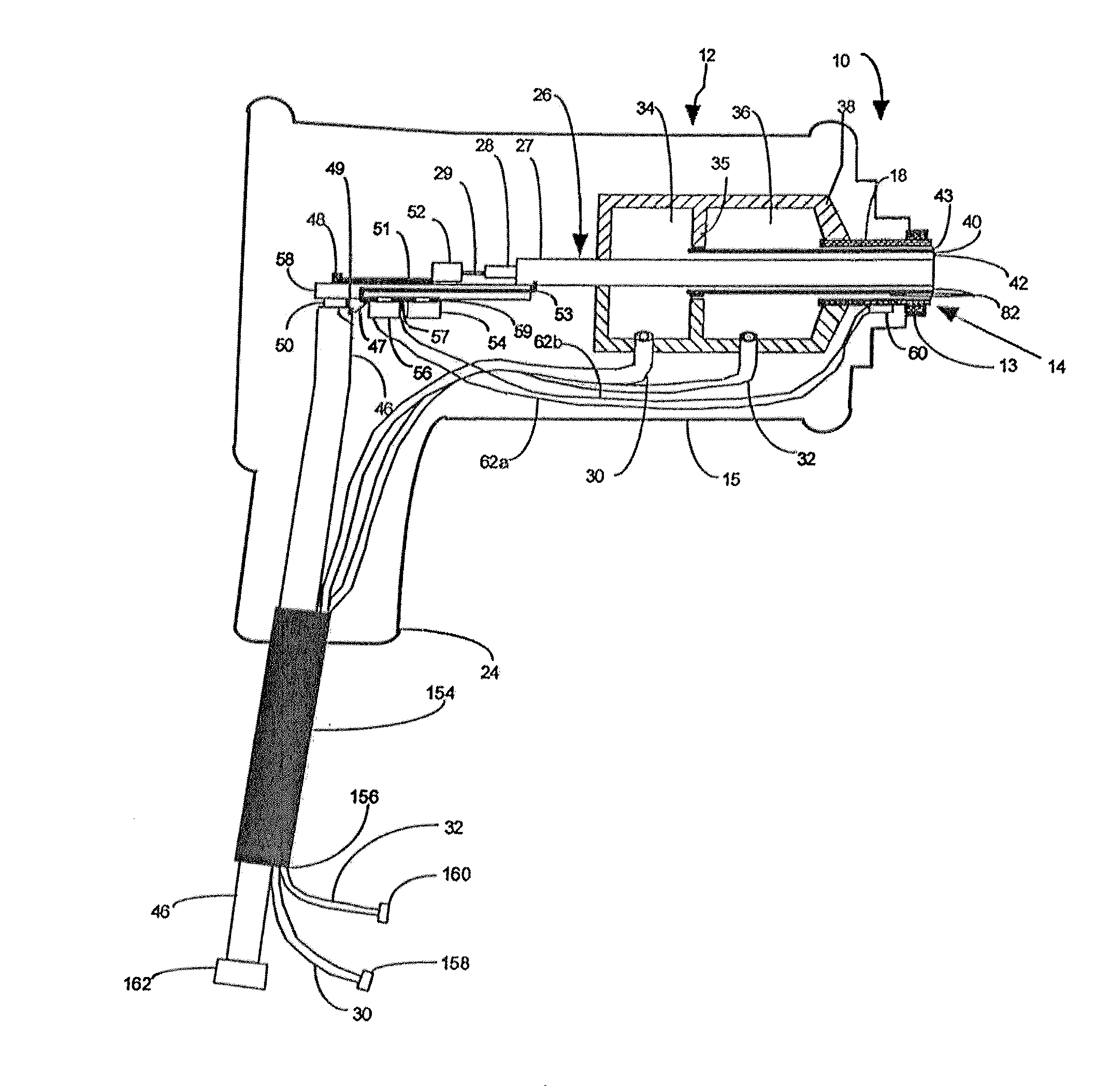
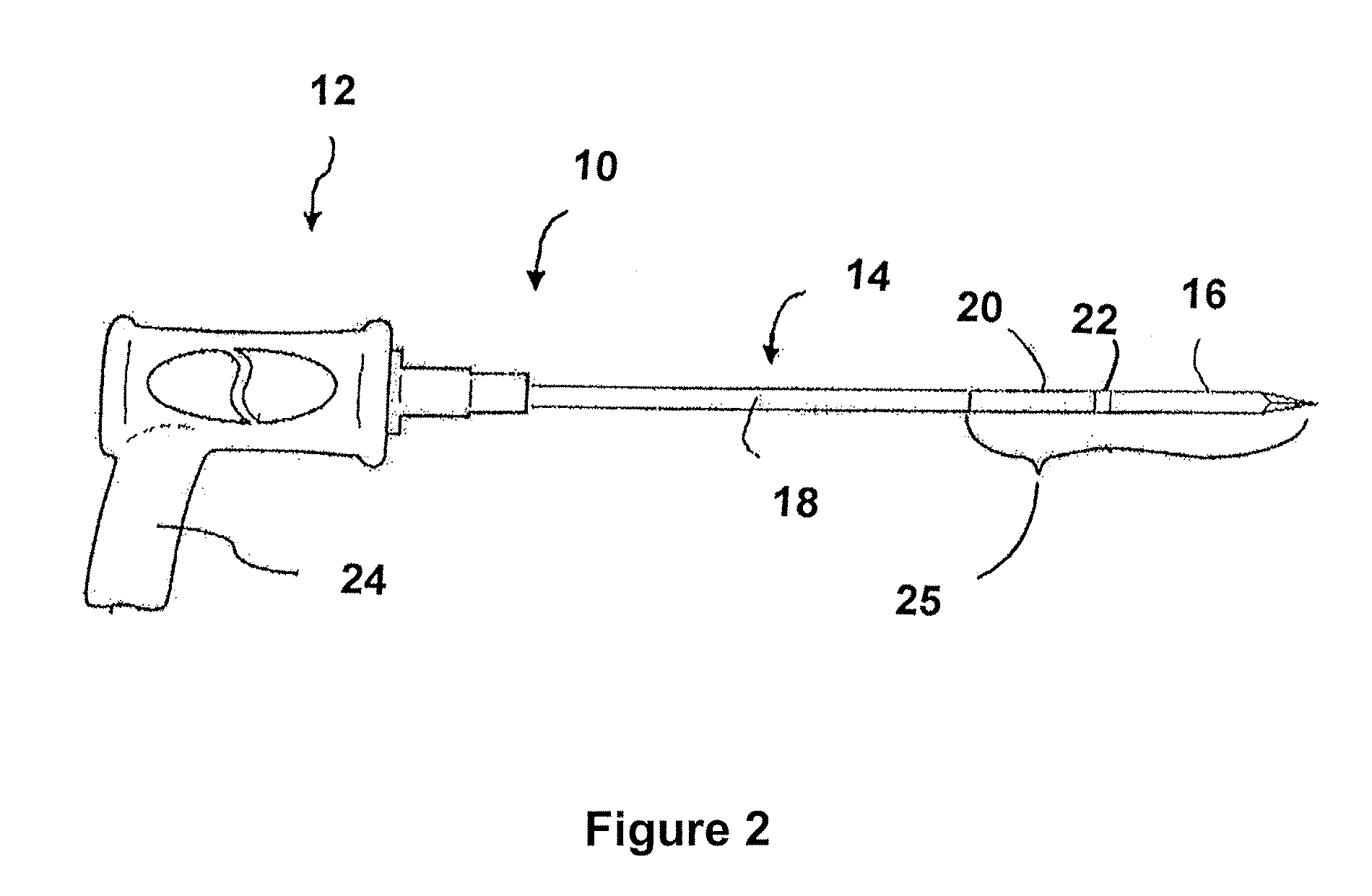
[0019]A system of the invention, as described above, can provide the use of either 915 MHz microwaves or 2450 MHz microwaves during different treatment procedures or can provide both 915 MHz microwaves and 2450 MHz microwaves during the same treatment procedure under common control by the single controller. Typically, when treating cancerous tumors, there may be multiple tumors where some are large and some are small. A combined frequency system enables patient set up for multiple tumors or even extended and larger portions of tumors to be treated using both frequencies simultaneously, multiplexed or time switched between frequencies, or sequentially with the same patient treatment set-up and system. Further, the system can provide independent automatic control and treatment of different target tumor zones automatically controlled by the common system controller, typically a digital computer, using a common interface to provide an operator with much easier and more practical treatment planning, set-up, and delivery. Having a fully integrated system with the same power supply, computer controller, computer interface display, computer control software, and fans for providing cooling air flow to the single power supply all lead to major cost savings and space savings compared to having a separate system for each frequency. Further, the system can provide the advantages of using common tissue temperature monitoring and control, maintaining treatment data records, and reduced sedation times for the patient with more rapid treatment delivery. Any applicator adapted for use with 2450 MHz can be connected to the 2450 MHz power output connector and any applicator or applicators adapted for use with 915 MHz can be connected to the 915 MHz power output connectors. A 915 MHz applicator satisfactory for use with the system is shown and described in detail in copending parent application Ser. No. 12 / 620,002 incorporated herein by reference.
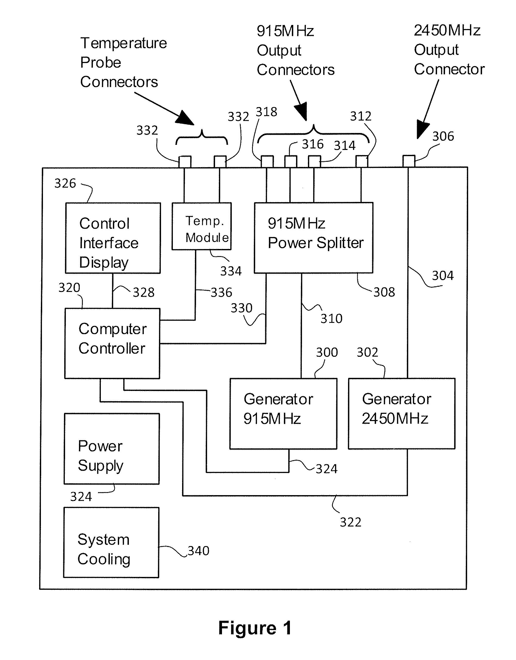
[0021]In the one embodiment, the 915 MHz signal generator and the 2450 MHz signal generator can each be separate narrow band tuned microwave generators that can provide relatively high efficiency of input vs. output power of typically 50% to 70%. A generator that is variable in frequency, such as a tunable broadband generator which can be adjusted over a frequency range that would include 915 MHz and 2450 MHz typically operates at much lower efficiency between about 6% to possibly 20%. Thus, the use of the separate narrow band tuned microwave generators provides much higher power efficiency to the system. The poor efficiency of the variable frequency microwave power generator requires much higher input power which means that the power supply supplying the input power to such a variable frequency signal generator would need to be more than 3 times larger and higher rated than a power supply supplying a single narrow band generator, and still much larger than a power supply capable of supplying power to two narrow band generators simultaneously. The larger the power supply, the more heat generated which requires more airflow cooling and fan noise to remove the extra internally generated heat, and the more heat being discharged into and heating the treatment room. The increased system efficiency provided by the increased efficiency of the narrow band tuned microwave generators allows much smaller equipment packaging, lower cooling noise, and less heat discharged into the treatment environment.
[0022]While the system can provide for simultaneous operation of both the 915 MHz signal generator and the 2450 MHz signal generator so that, if and when desired, both 915 MHz and 2450 MHz microwave power can be supplied to both the 915 MHz applicator or applicators and the 2450 MHz microwave applicator simultaneously, such a system requires a power supply having sufficient power output to power both generators at their maximum power requirement simultaneously. Substantially the same results can be obtained by operating only one of the microwave signal generators at a time, with the capability of quickly switching between the signal generators, thereby lessening the power output requirements for the power supply and the overall system. Since the tissue heating is a result of the average power absorption in the tissue, it does not matter whether the power applied is pulsed, time sequenced, or continuous wave if the average power is the same and the time cycle is not more than up to about twenty seconds. With such an arrangement, a physician can install both 915 MHz and 2450 MHz applicators during an applicator positioning period and have the system ready to apply treatment through an array of 915 MHz antennas and sequentially or periodically through the 2450 MHz antenna. This can be provided by a timed switching between the two signal generators, or switching under manual control when the physician is ready to switch to the other antenna and frequency. This can be done quickly moving from one treatment field to the other possibly neighboring field where a rapid back and forth switching (multiplexing) allows the ablated zone of the first treatment to retain its temperature while applying microwave energy to the other, and back and forth to maintain the treatment temperature in both fields or zones. If time switched during the same procedure, the whole region will remain at ablation temperatures provided by time gated switching between the two frequency modes to provide a larger and more tailored ablation pattern than that which the phased array at 915 MHz might achieve alone. This can also provide for simultaneous heating of smaller tumors at 2450 MHz while larger tumors are treated at 915 MHz by having the system doing time switching of its operation between the two frequency operating modes. This switching is possible only with the provision of the two separate generators to which the appropriate applicators can be connected through separate connections and both generators are controlled by a common controller.

Problems solved by technology

Above a threshold temperature of about 41.5 degrees C., substantial thermal damage occurs in most malignant cells if this temperature is maintained for a sufficiently long time, typically longer than about 120 minutes.
For example, when heating is combined with radiation, it is desirable to maintain the temperature within the diseased tissue within the range of about 42 to about 45 degrees C. Higher temperatures are usually undesirable when a combined treatment modality is used because higher temperatures can lead to microvessal collapse causing resistance to radiation therapy and decreasing the amount of systemic chemotherapy reaching the tumor if the tumor has suffered vascular damage.
Lower temperatures are undesirable because they can fail to provide adequate therapeutic effect.
Therefore, it is important to control the temperature in the treated tissue within the desired range for multi-modality treatments and not allow heating of the tissue in the tumor or around the tumor to above 45 degrees C. where tissue damage from other treatments may be compromised.
The outer margin of the overall heat distribution in the treated tissue volume may then result in damage to normal tissue if such normal tissue is overheated.
Therefore, for prolonged coagulation or ablation treatments where the coagulation or ablation volume is maintained at very high temperatures, there is a high risk of damage to surrounding normal tissues.
However, even in these locations, it is important to limit and control the destruction of normal tissue surrounding the tumor or other tissue to be treated.
The process of heating very rapidly to high temperatures that is common in coagulation and ablation treatments may utilize a rather short exposure time.
However, if such treatments continue for multiple minutes, the blood flow and thermal conduction of the tumor and surrounding tissues will modify the temperature distribution to result in a less predictable heat distribution because the changes occurring in blood flow in such a heated region may not be predictable.
Typically, diseased tissue such as cancerous tumors may not have a significant pain sensation, but normal tissues would be more likely to have pain limitations on treatment, particularly skin tissue of the patient.
Even when properly placed, however, it has been difficult to ensure that adequate heat is developed in the diseased tissue without overheating surrounding healthy tissue.
Further, with applicators operating at higher power levels to produce the needed higher temperatures for coagulation and ablation, there is a tendency for the cable in the portion of the applicator leading from outside the body to the location of the application of the electromagnetic energy in the applicator to heat to undesirably high temperatures which can cause thermal damage to the normal tissue through which the applicator passes to reach the diseased tissue to be treated.
Electromagnetic energy tissue treatment systems are generally expensive and are generally large taking up limited space in a treatment area.
However, many treatment centers will not be able to afford having two or more separate complete systems or may not have the space for two or more separate complete systems.
It is very inconvenient in such a critical procedure not to have the desired ablation equipment in-place and ready for treatment use prior to the pretreatment images taken just prior to treatment.
However, having two or more different and separate systems ready for use is not generally practical.

Method used


Image

  • Multiple Frequency Energy Supply and Coagulation System
  • Multiple Frequency Energy Supply and Coagulation System
  • Multiple Frequency Energy Supply and Coagulation System

Examples


Embodiment Construction

[0031]Reference will now be made to the exemplary microwave energy signal embodiments illustrated in the drawings, and specific language will be used herein to describe the same. It will nevertheless be understood that no limitation of the scope of the invention is thereby intended. For example, any combination of microwave and / or radiofrequency energy signals can be used. Alterations and further modifications of the inventive features illustrated herein, and additional applications of the principles of the inventions as illustrated herein, which would occur to one skilled in the relevant art and having possession of this disclosure, are to be considered within the scope of the invention.

[0032]FIG. 1 is a block diagram showing an embodiment of the microwave energy supply system of the invention. Referring to FIG. 1, an example embodiment of the microwave energy supply system of the invention includes a 915 MHz signal generator 300 and a 2450 MHz signal generator 302. Each of these g...


PUM


Abstract

An electromagnetic energy supply system for supplying electromagnetic energy signals to an applicator for applying the electromagnetic energy signals to tissue for heating such tissue can supply electromagnetic energy signals of at least one selected frequency of a plurality of frequencies available for selection. The system includes a plurality of individual electromagnetic signal generators each adapted to generate signals of a particular frequency, such as two microwave energy signal generators with one operating at 915 MHz and one operating at 1450 MHz. A system controller coordinates operation of the generators. Each generator is connected to connectors for connecting an applicator or array of applicators for applying the selected frequency electromagnetic energy signals to the tissue to be heated. A power splitting circuit can provide multiple connectors tuned for one or for more than one applicator to be connected. The system can provide a treatment using a single selected frequency, a plurality of selected frequencies simultaneously, or can switch between selected frequencies.

Description

RELATED APPLICATIONS[0001]This is a continuation-in-part of co-pending application Ser. No. 12 / 620,002, filed Nov. 17, 2009, of co-pending application Ser. No. 12 / 689,195, filed Jan. 18, 2010, both entitled Microwave Coagulation Applicator and System, of co-pending application Ser. No. 12 / 794,667, filed Jun. 4, 2010, entitled Microwave Coagulation Applicator and System with Fluid Injection, and of PCT Application No. PCT / US2010 / 57127, filed Nov. 17, 2010, entitled Microwave Coagulation Applicator and System, all hereby incorporated herein by reference.BACKGROUND OF THE INVENTION[0002]1. Field[0003]This invention relates to heat treatment of living body tissue such as tissue ablation, coagulation, and hyperthermia, and particularly to the creation of heat in such tissue by the application of electromagnetic (EM) energy, such as microwave energy and / or radiofrequency energy, to such tissue. Further, the invention relates particularly to energy supply systems for generating desired ele...

Claims


Application Information

Patent Timeline
IPC IPC(8): A61B18/18
CPCA61B2018/0019A61B18/1815
Inventor TURNER, PAUL F.HAGMANN, MARK
Owner ENDOCARE
Learn More