Method and system for determining the amplitude and/or phase of the output signal for a transmission body depending on the amplitude of the input signal

a transmission body and input signal technology, applied in the field of methods and systems for determining the amplitude and/or phase of the output signal of the transmission link, can solve the problems of excessively expensive time and function, unsatisfactory amplitude and phase distortion of the signal to be amplified, etc., and achieve the effect of maximum process security and minimal processing tim

Active Publication Date: 2011-05-26
ROHDE & SCHWARZ GMBH & CO KG
View PDF11 Cites 0 Cited by
  • Summary
  • Abstract
  • Description
  • Claims
  • Application Information

AI Technical Summary

Benefits of technology

The invention is therefore based upon the object of providing a method and a system for determining the amplitude and / or phase of the output signal of a transmission link dependent upon the amplitude of the input signal, which are optimized with regard to minimal processing time and maximum process security.

Problems solved by technology

This nonlinear transmission behavior leads to undesirable amplitude and phase distortions of the signal to be amplified.
In calibrating power amplifiers in the receiver and / or transmitter units of mobile telephones, the procedure described in WO 99 / 05784 A1 of measuring two signals, at the input and at the output of the power amplifier, and the additionally-required synchronization of the two signals is excessively costly in terms of time and functions.

Method used


Image

  • Method and system for determining the amplitude and/or phase of the output signal for a transmission body depending on the amplitude of the input signal
  • Method and system for determining the amplitude and/or phase of the output signal for a transmission body depending on the amplitude of the input signal
  • Method and system for determining the amplitude and/or phase of the output signal for a transmission body depending on the amplitude of the input signal

Examples


Embodiment Construction

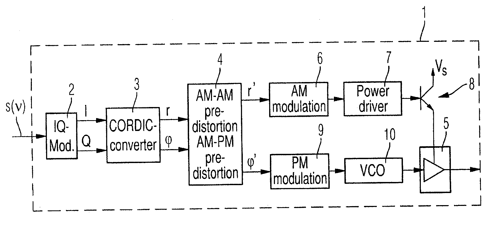
Before describing a system according to the invention and a method according to the invention for determining the amplitude and phase response of a general transmission link with reference to FIG. 2 and FIG. 4, the structure and respective functioning of a polar modulator for a mobile telephone will first be presented with reference to FIG. 1, of which the calibration can be regarded as a preferred application of the method according to the invention and the system according to the invention for measuring the amplitude and phase characteristic of a transmission link.

The polar modulator 1 is supplied from a signal source, which is not shown in FIG. 1, with a symbol sequence s(n) to be transmitted. With the assistance of a carrier signal, an IQ modulator 2 generates from the signal sequences s(ν) the in-phase and quadrature components I and Q of a quadrature signal to be transmitted by the mobile telephone. The in-phase and quadrature components I and Q of the quadrature signal are co...


PUM


Abstract

A method and a system for determining the amplitude and/or the phase of the output signal of a transmission link dependent upon the amplitude of the input signal (AM-AM and/or AM-PM characteristic) impresses a test signal (s(t)) on the transmission link, measures the response signal (e(t)) resulting from the test signal (s(t)) by amplitude and/or phase distortion in the transmission link and determines the amplitude response (|e(t)|) of the response signal (e(t)) and/or the phase responses (φS(t), φE(t)) of the test signal (s(t)) and of the response signal (e(t)) dependent upon the amplitude response (|s(t)|) of the test signal (s(t)). The amplitude response (|s(t)|) of the test signal (s(t)) consists of several first and second response segments with constant amplitude values over the duration (ΔT) of the respective first or second response segment.

Description

BACKGROUNDEmbodiments of the invention relate to a method and a system for determining the amplitude and / or phase of the output signal of a transmission link dependent upon the amplitude of the input signal (AM-AM and AM-PM characteristic).SUMMARYCommunications transmission links, for example, amplifiers in the receiver or transmitter unit of a mobile telephone, provide non-linear transmission behavior. This nonlinear transmission behavior leads to undesirable amplitude and phase distortions of the signal to be amplified. In order to compensate for these undesired distortion effects, it is already known that an equalizing network, of which the characteristic is ideally designed to be inverse to the non-linear transmission characteristic of the transmission link, can be connected in series to the non-linear transmission link.The amplitude and phase of the output signal of the transmission link dependent upon the amplitude of the input signal (AM-AM and AM-PM characteristic) are there...

Claims


Application Information

Patent Timeline
Patent Type & Authority Applications(United States)
IPC IPC(8): H04B17/00
CPCH04B17/13H04B7/005H04B17/00H04L27/34
Inventor LORENZEN, ROLF
Owner ROHDE & SCHWARZ GMBH & CO KG
Why Eureka
Try Eureka