Guide bar for a motor chainsaw and method for producing a guide bar

a technology of guide bars and chainsaws, which is applied in the direction of manufacturing tools, furnaces, heat treatment devices, etc., can solve the problems of large wear on the guide bars of motor chainsaws, large wear on the deflection section of the guide bars, and large wear on the guide bars

Active Publication Date: 2022-11-01
ANDREAS STIHL AG & CO KG
View PDF19 Cites 0 Cited by
  • Summary
  • Abstract
  • Description
  • Claims
  • Application Information

AI Technical Summary

Benefits of technology

[0009]It has been found that by hardening the guide surfaces formed at the side plates at the longitudinal sides as well as at the guide bar tip a significant reduction of the susceptibility of the guide bar to wear can be achieved. At the longitudinal sides as well as at the guide bar tip, a guide bar has preferably at least one hardened region with increased hardness compared to the middle region of the side plates. The middle region of the side plates comprises at least the region in which the longitudinal center axis of the guide bar, in a side view perpendicular to the plane of the side plates, extends in a longitudinal section of the guide bar which is arranged between the clamping section and the deflection section. The hardness of the middle region of the side plates corresponds preferably to the hardness of the base material of the side plates prior to hardening at the longitudinal sides and at the guide bar tip.
[0015]In an advantageous embodiment, an intermediate region extends at the guide surfaces between the longitudinal sides and the deflection section, respectively; the intermediate section has a reduced hardness compared to the hardened region. The intermediate region enables a very simple manufacture of the hardened regions at the longitudinal sides and at the deflection section. The hardened regions at the longitudinal sides and at the deflection section can be produced such that the hardened regions overlap each other, in particular slightly. The overlap region forms the intermediate region because the two hardening zones influence each other mutually so that a reduced hardness results in the intermediate region. The intermediate region is preferably arranged at a distance from the guide bar tip. The intermediate region is preferably positioned such that in the intermediate region a comparative minimal load is to be expected. The intermediate region is preferably arranged at a distance from the guide bar tip which amounts to 40% to 70% of the height of the guide bar. The height of the guide bar is measured in this context at a side plate, i.e., a flat side of the guide bar, and parallel to the plane of the guide bar and perpendicularly to the longitudinal center axis of the guide bar. The plane of the guide bar is the plane which contains the longitudinal center axis and extends centrally between the side plates, i.e., parallel to the outer sides of the guide bar. The flat side of the guide bar forms an outer side of the guide bar which extends at the side plate.
[0017]A longitudinal section is preferably provided between the deflection section and the clamping section. Preferably, at least 10%, in particular at least 50%, preferably at least 90%, of the length of the intermediate region measured parallel to the longitudinal center axis is located within the longitudinal section. Since the intermediate region is located at least partially, in particular across at least 10%, preferably across significantly more than 10% of its length, outside of the deflection section, it is achieved that the guide surface in the deflection section is formed to a large extent by the hardened region. In this way, the wear at the free end of the guide bar can be reduced. Advantageously, the intermediate region comprises a length measured parallel to the longitudinal center axis of less than 20 mm. Since the intermediate region is embodied comparatively short, a hardened guiding surface at both side plates can be achieved to a large extent by a simple hardening process. Preferably, the length of the intermediate region is less than 15 mm, preferably less than 10 mm.
[0022]In regard to a method for producing a guide bar for a motor chainsaw, it is provided that the guide bar is inductively hardened at the longitudinal sides as well as at the guide bar tip. Inductive hardening can be performed in a simple way.
[0024]Preferably, both longitudinal sides are hardened simultaneously. In this way, minimal processing times for the hardening process can be obtained. The longitudinal sides are preferably hardened in a continuous process in which the guide bar is moved in the direction of the longitudinal center axis past two inductors which, in regard to the longitudinal center axis, are stationary but are movable transversely to the longitudinal center axis. The arrangement of the inductors so as to be movable transversely to the longitudinal center axis makes it possible that the inductors can follow the curvature of the guide bar in the longitudinal section as the guide bar moves past the inductors. The inductors in this context are movable in particular perpendicularly to the longitudinal center axis. In this way, a constant depth of the hardened regions can be achieved within the limits of the obtainable tolerances. Preferably, at least one part of the deflection section that comprises the guide bar tip is hardened with an inductor whose shape is matched to the shape of the part of the deflection section that is to be hardened. An inductor whose shape is matched to the shape of the part to be hardened is also referred to as shaped inductor. With two inductors which are arranged at the longitudinal sides of the guide bar, a circumferential hardening of the deflection section is not possible without problems. An inductor moving past the entire longitudinal side and the deflection section of the guide bar causes a longer processing time. A problem of a shaped inductor is that the entire contour to be hardened is simultaneously hardened and therefore the energy introduced into the guide bar is very high. Since only the deflection section is hardened with a shaped inductor while the longitudinal sides of the guide bar are hardened by a continuous process, the energy introduction into the guide bar during hardening can be kept at an acceptable level and the required processing time is kept at a minimum at the same time.
[0025]The present method for producing a guide bar provides that the assembled guide bar is locally inductively hardened. Accordingly, instead of individual parts of the guide bar that are not yet assembled, for example, side plates of the guide bar, being hardened and subsequently assembled, the finish-assembled guide bar as a whole is locally hardened. In this way, hardened regions are produced at the guide surfaces at both side plates at the same time. This also leads to a reduction of the processing time.

Problems solved by technology

Guide bars for motor chainsaws are subject to great wear during operation.
Particularly the deflection section of the guide bar is subjected to great wear due to the high mechanical load in operation.
The construction of such guide bars is however comparatively complex.

Method used


Image

  • Guide bar for a motor chainsaw and method for producing a guide bar
  • Guide bar for a motor chainsaw and method for producing a guide bar

Examples


Embodiment Construction

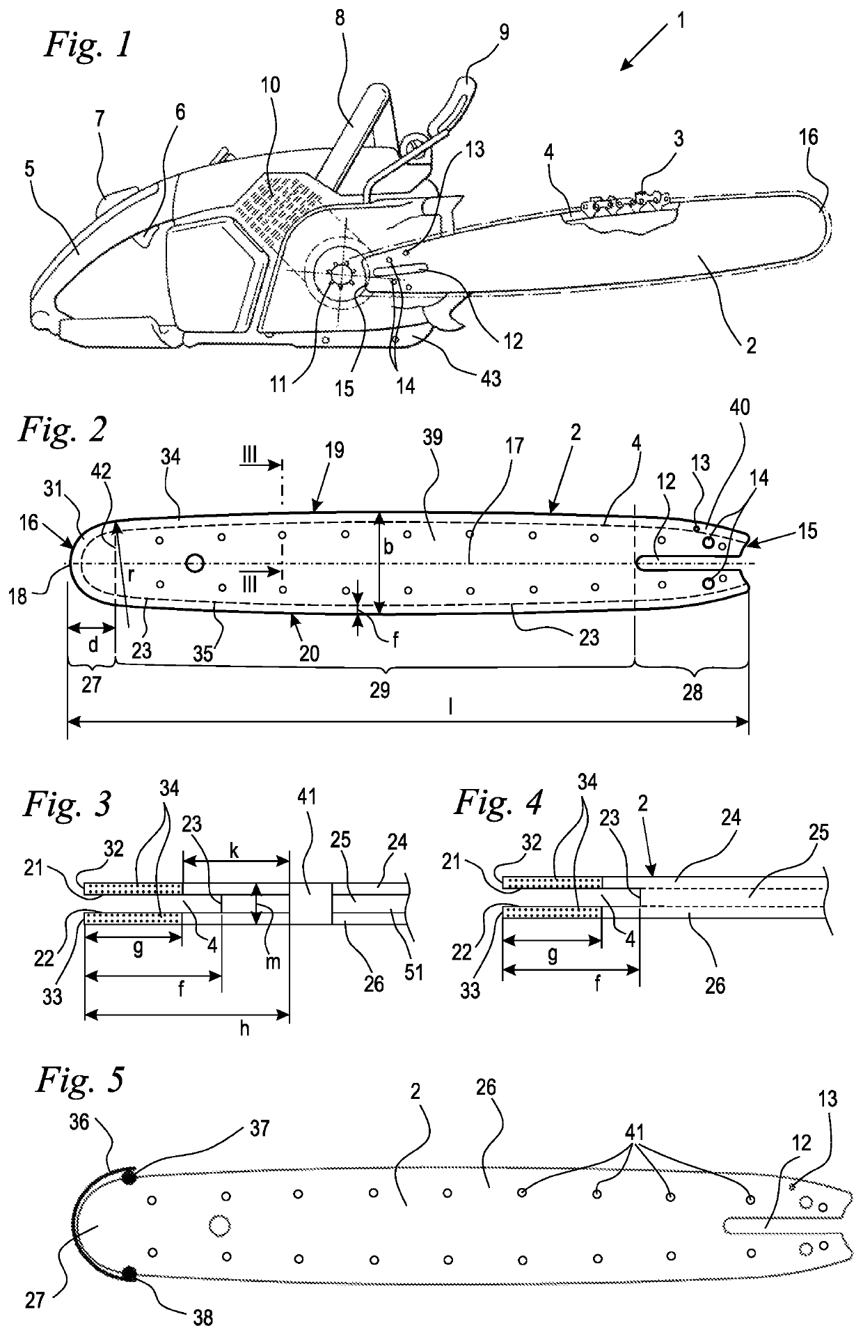
[0035]FIG. 1 shows schematically a motor chainsaw 1 comprising a guide bar 2. The guide bar 2 comprises a guide groove 4 in which a saw chain 3 is guided in circulation. The saw chain 3 is guided across a drive pinion 11 which in operation is rotatingly driven by a drive motor 10 and in this way moves the saw chain 3 in circulation about the circumference of the guide bar 2. The drive motor 10 is schematically illustrated in FIG. 1 as an internal combustion engine. The drive motor 10 however can also be an electric motor which is supplied with energy by a rechargeable battery or by a power cord. The guide bar 2 comprises a clamping end 15 with which the guide bar 2 is secured at a housing 43 of the motor chainsaw 1. The drive pinion 11 is positioned adjacent to the clamping end 15. The end of the guide bar 2 which is remote from the housing 43 forms a free end 16 at which the saw chain 3 is deflected. The guide bar 2 comprises near the clamping end 15 a guide slot 12 through which c...


PUM

PropertyMeasurementUnit
radiusaaaaaaaaaa
lengthaaaaaaaaaa
lengthaaaaaaaaaa

Abstract

A guide bar for motor chainsaws has side plates and a middle section between the side plates connected fixedly and non-movably to the side plates. The side plates form a clamping section and a deflection section opposite the clamping section. A guide groove extends circumferentially about the guide bar. The middle section forms the guide groove bottom in the deflection section. A guide bar tip is located where the longitudinal center axis of the guide bar intersects the deflection section. The side plates each have a guide surface extending continuously across a first longitudinal side of the guide bar, the deflection section, and a second longitudinal side of the guide bar. The guide surfaces of the side plates have hardened regions at the first and second longitudinal sides and at the guide bar tip with a hardness greater than a hardness of a middle region of the side plates.

Description

BACKGROUND OF THE INVENTION[0001]The invention relates to a guide bar for a motor chainsaw, wherein the guide bar comprises a clamping section and a free end, wherein at the free end a deflection section is arranged. The guide bar comprises two one-piece side plates, wherein the side plates extend from the clamping section to the deflection section and form the deflection section. The guide bar comprises a circumferentially extending guide groove. The guide bar comprises a middle section arranged between the side plates, wherein the middle section forms the bottom of the guide groove in the deflection section. The middle section is connected fixedly and non-movably to the side plates. The guide bar comprises a guide bar tip where a longitudinal center axis of the guide bar intersects the deflection section. The guide bar comprises a first longitudinal side and a second longitudinal side. Each side plate comprises a guide surface which extends continuously across the first longitudin...

Claims


Application Information

Patent Timeline
Patent Type & Authority Patents(United States)
IPC IPC(8): B27B17/02B23D57/02
CPCB27B17/02B23D57/023B23D57/02C21D9/0068C21D1/10C21D2221/00B27B17/025Y02P10/25
Inventor LUX, THOMASLEIENDECKER, MARTINMITREGA, DAVID
Owner ANDREAS STIHL AG & CO KG
Why Eureka
Try Eureka