
Lifetime extending and performance improvements of optical fibers via loading

a technology of optical fibers and lifetime extensions, applied in the field of optical fibers, can solve the problem that the average power/spectral density carried by optical fibers is the damage threshold of fibers, and achieve the effect of reducing or eliminating the degradation

Active Publication Date: 2011-05-19
NKT PHOTONICS
View PDF8 Cites 28 Cited by
  • Summary
  • Abstract
  • Description
  • Claims
  • Application Information

AI Technical Summary

Benefits of technology

[0004]The object of the present invention is to provide a fiber where such degradation is either eliminated or reduced.
[0024]After deuterium and / or hydrogen loading, the fiber is preferably annealed. The anneal enables splicing the fiber to other fibers (plasma heating of hydrogen / deuterium, such as in fusion splicing, may be explosive) and reduces any added photosensitivity due to these molecules. However, as discussed below, an anneal may also serve other functions such as providing increased lifetime of the fiber and increased spectral stability of embodiments of supercontinuum light sources according to the invention. Furthermore, in one embodiment the fiber is annealed prior to loading of the fiber, such as to relieve defects or stress in the fiber material. In one embodiment the fiber is anneal as a part of the drawing process. In one embodiment fiber is annealed between pulling the fiber and coating of the fiber. In one embodiment the temperature of this anneal is equal to or less than the temperature applied to the preform when pulling the fiber, such as 90% or less of that temperature, such as 80% or less of that temperature, such as 70% or less of that temperature, such as 60% or less of that temperature, such as 50% or less of that temperature, such as 40% or less of that temperature, such as 30% or less of that temperature, such as 20% or less that temperature, such as 10% or less that temperature. In one embodiment the anneal is a flash anneal providing a relatively brief high energy irradiation.
[0046]As the fiber according to the invention has no or reduced degradation due to exposure to high peak power such a system may have an extended lifetime of operation depending on the significance of the fiber performance and life-time relative to that of other components in the system.

Problems solved by technology

One limitation of the average power / spectral density carried by an optical fiber is the damage threshold of the fiber.

Method used


Image

  • Lifetime extending and performance improvements of optical fibers via loading
  • Lifetime extending and performance improvements of optical fibers via loading
  • Lifetime extending and performance improvements of optical fibers via loading

Examples


Embodiment Construction

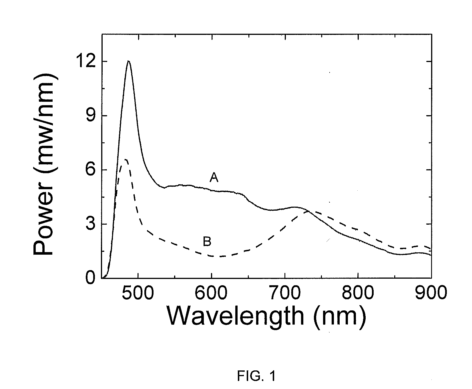
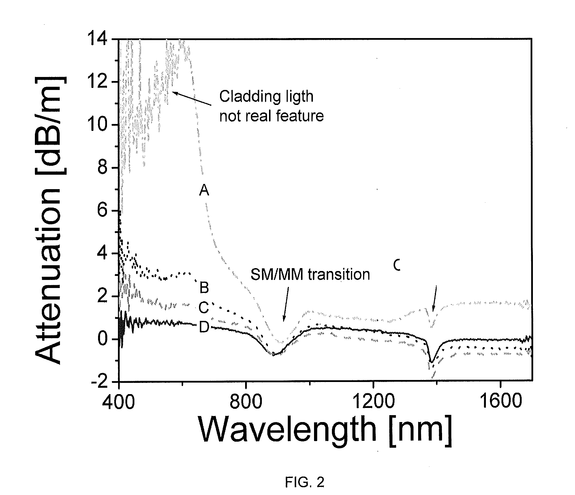
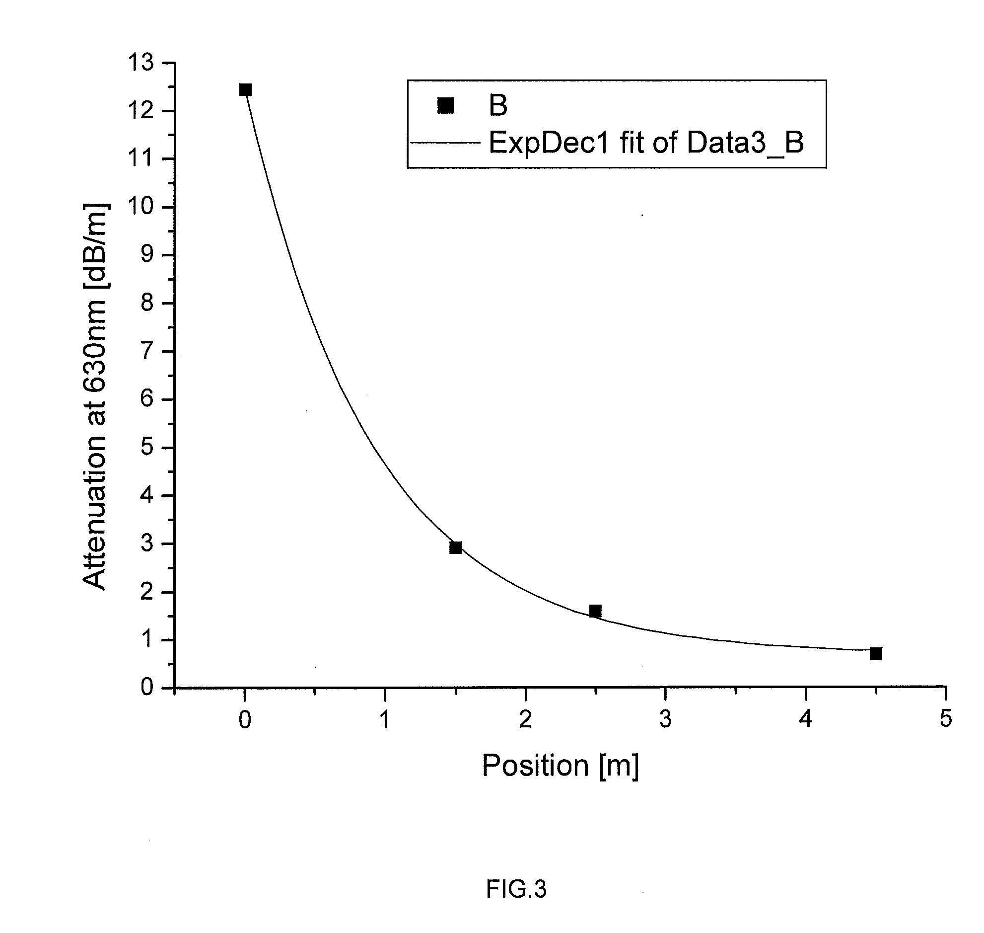
[0071]In the following some examples will comprise discussion of the invention based on measured data. The conclusions drawn from these should not necessarily be considered limited to the specifics of the underlying experiments.

[0072]Super Continuum Generation in Microstructured Fibers

[0073]In one embodiment of the invention the optical fiber is a microstructured optical fiber. Microstructured optical fibers are a relatively new technical field where the properties of the waveguide may be designed with a relatively large degree of freedom. Such fibers are commonly made of pure silica comprising a pattern, often made of holes or doped glass, extending in the longitudinal direction of the fiber. The freedom of design makes such fibers interesting for application requiring specific non-linear properties of the fiber. One such application is supercontinuum generation wherein a fiber based source is cable of generating a wide spectral output. Supercontinuum (SC) generation in microstruct...


PUM


Abstract

The invention relates to an optical fiber comprising a core and a cladding comprising a core material and a cladding material, respectively, wherein said fiber is a non-linear microstructured optical fiber, said microstructured optical fiber being obtainable by a method comprising loading with hydrogen and / or deuterium and optionally anneal and / or irradiation hereby the lifetime of the fiber may be extended in high power applications.

Description

TECHNICAL FIELD[0001]The invention relates specifically to an optical fiber comprising a core and a cladding comprising a core material and a cladding material, respectively.BACKGROUND ART[0002]Guiding of relatively high powers in an optical fiber may have relevance for several commercial applications such as such as guiding of surgical and / or therapeutic light, optical sensing, and materials processing. Among such applications is transport of optical energy and utilizing non-linear effects in the fiber which are commonly more pronounced with higher optical power inside the fiber. The optical power may be continuous wave (CW), pulsed or a mixture thereof. High optical power inside a fiber may be particularly pronounced with pulsed light where a high peak power may be obtainable even while having a relatively modest average power.[0003]One limitation of the average power / spectral density carried by an optical fiber is the damage threshold of the fiber. The input facet or the first fe...

Claims


Application Information

Patent Timeline
IPC IPC(8): G02B6/02B05D3/02H01S3/00
CPCG02B6/02333G02B6/02342G02F1/365G02B6/4492G02B6/4296G02F1/3528G02B6/44382A61B1/06G02B6/0006G02B6/02319H01S3/302
Inventor THOMSEN, CARSTEN L.ANDERSEN, THOMAS VESTERGAARD
Owner NKT PHOTONICS
Learn More