
Visulation of geologic features using data representations thereof

a geologic feature and data technology, applied in image data processing, instruments, image enhancement, etc., can solve the problems of inability to realistically model many 3-d geologic features, lack of integrated segmentation capabilities, and time-consuming manual task of image and subsequent identification of geologic features in data, etc., to achieve easy segmentation, improve feature structure, and improve the effect of feature structur

Inactive Publication Date: 2011-05-19
CGG JASON NETHERLANDS
View PDF56 Cites 201 Cited by
  • Summary
  • Abstract
  • Description
  • Claims
  • Application Information

AI Technical Summary

Benefits of technology

[0007]Image structure analysis techniques enhance feature structure using partial derivative information. This exemplary approach is powerful because it employs a combination of first and second order derivative information to differentiate between a wide variety of structures. These techniques are only beginning to be applied to the field of seismic interpretation and the information they generate remains to be explored for feature segmentation. This presents an opportunity to adapt image structure analysis in order to create representations for geologic features that can be used to allow for easier segmentation.
[0008]Surface segmentation separates features from background data using either an implicit or explicit representation of a surface. Up until recently, most published work in computer graphics and vision for imaging applications have used explicit surfaces constructed from triangles. Triangulated surfaces require extreme care to be taken when discontinuous topological changes occur and smoothness is difficult to guarantee. In addition, there is no guarantee that the result of an explicit surface will be physically realizable. Implicit surfaces are represented volumetrically using level set methods and have an advantage over explicit surfaces in how easily dynamic topological changes and geometric quantities, such as normals and curvatures, are determined. Also, the results of level set simulations are physically realizable implicit surface models, which is desirable when attempting to represent geologic features.
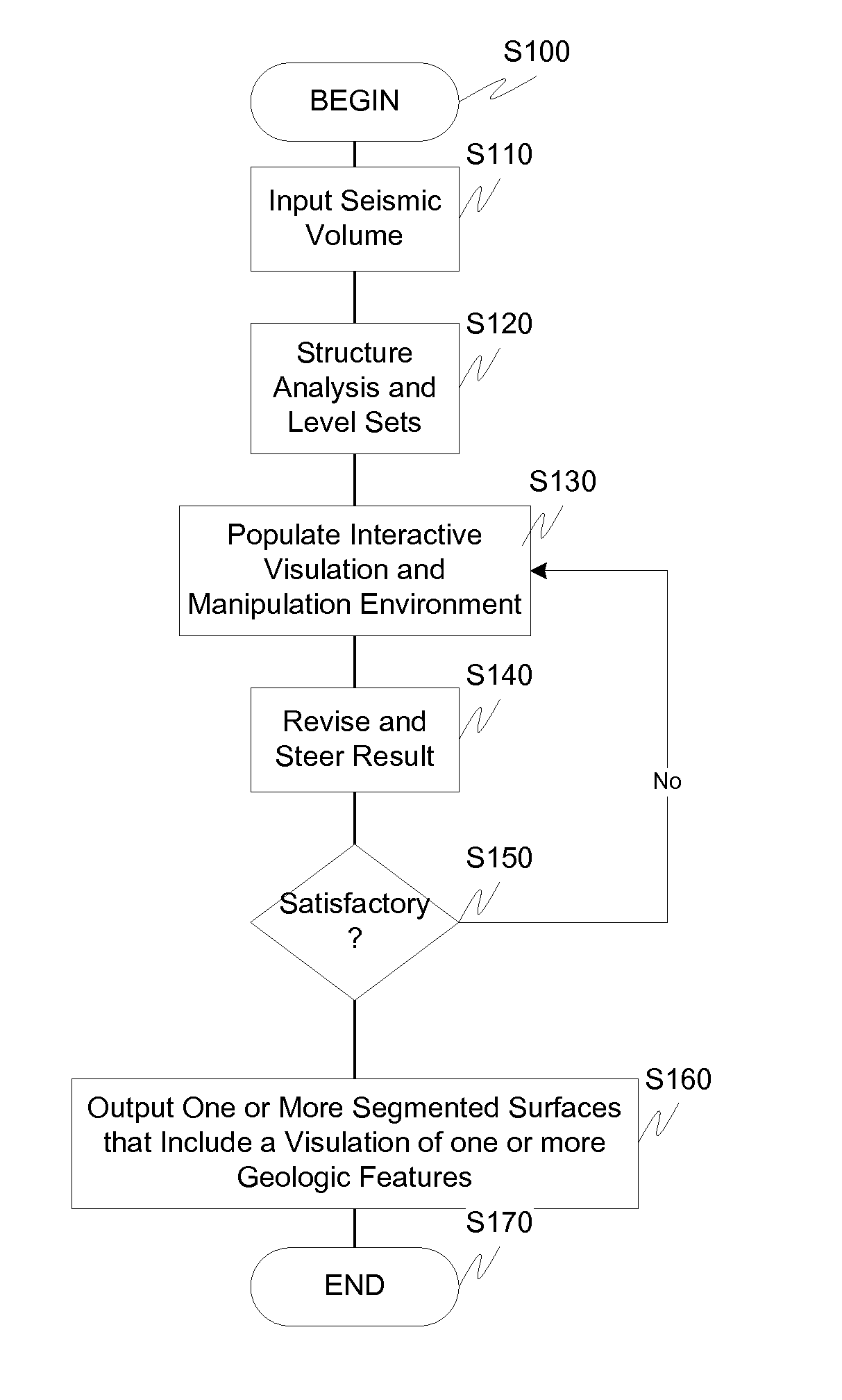
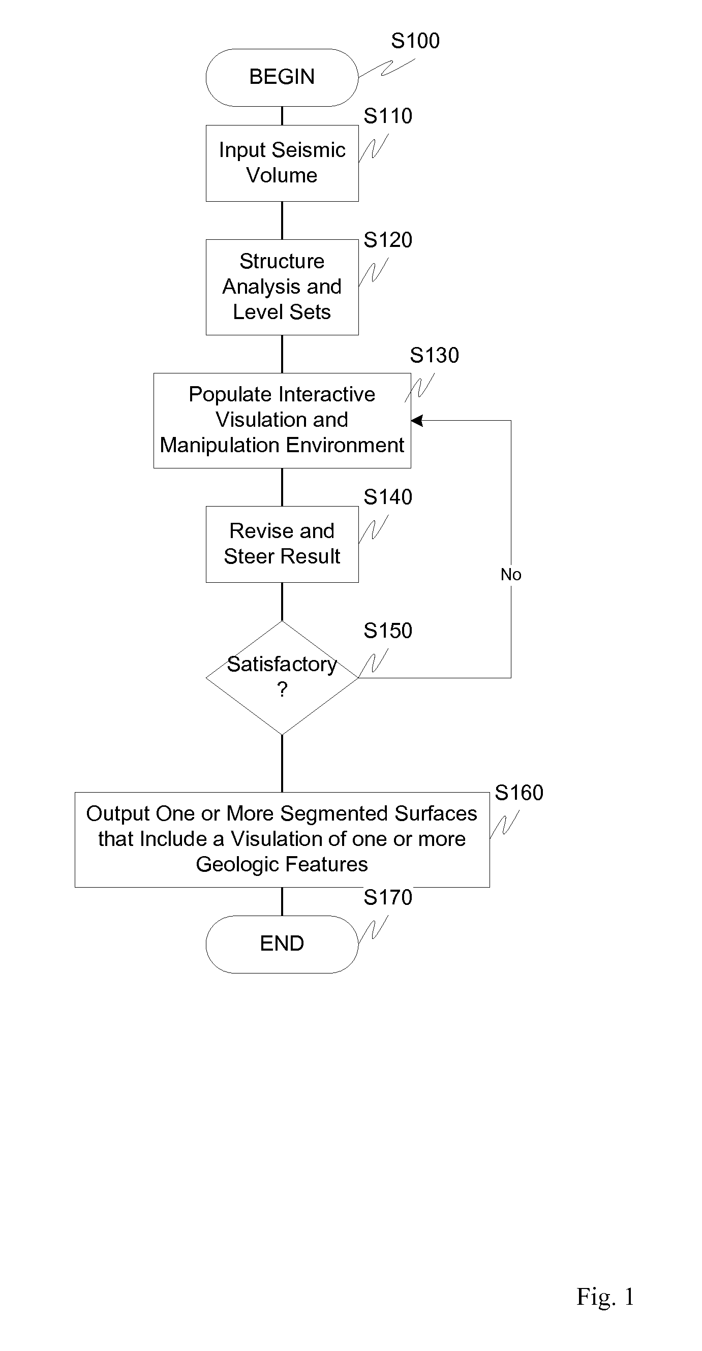
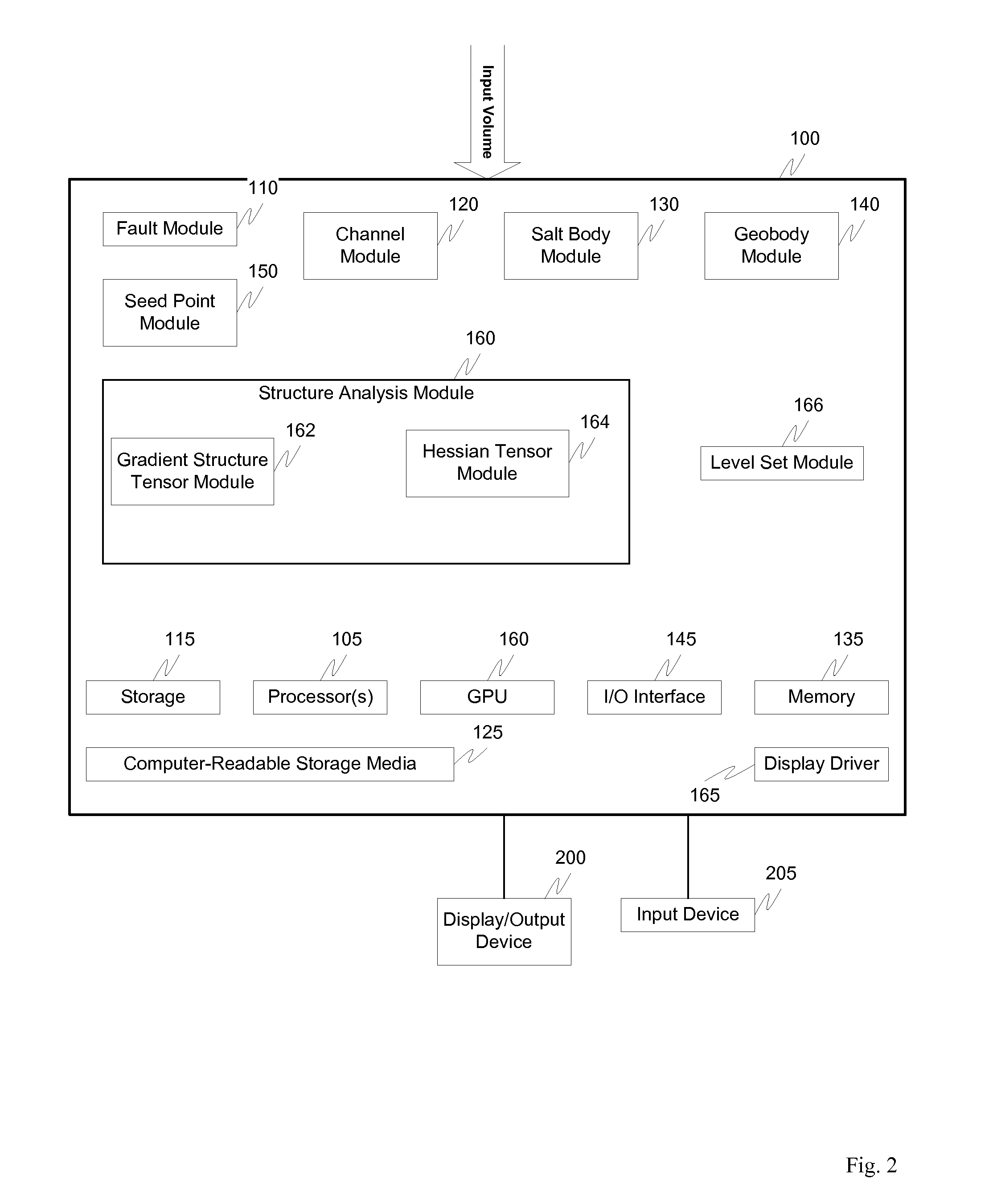
[0010]An exemplary embodiment of this invention therefore presents a unified approach that combines image structure analysis and implicit surface modeling in an Interactive “Visulation” Environment designed to segment geologic features. The IVE allows geoscientists to observe the evolution of surfaces and steer them toward features of interest using their domain knowledge. In accordance with one exemplary embodiment, the process is implemented on a GPU for increased performance and interaction. The resulting system is a surface-driven solution for the interpretation of 3-D seismic data, in particular for the segmentation and modeling of faults, channels, salt bodies and other geobodies.

Problems solved by technology

Three-dimensional seismic data has been used to explore the Earth's crust for over 30 years, yet the imaging and subsequent identification of geologic features in the data remains a time consuming manual task.
Most current approaches fail to realistically model many 3-D geologic features and offer no integrated segmentation capabilities.
Many real-world objects can be represented as an implicit surface but further interpretation of those surfaces is often severely limited, such as the growth and segmentation of plane-like and high positive curvature features.
Unfortunately, most of the easy oil fields in the world have already been discovered and therefore current exploration efforts focus on difficult to reach fields or missed plays in already developed fields.
Analyzing the seismic data used to locate reservoirs is a complex task due to the data's unique layered structure, the difficulty in identifying features, and the large size of data sets.
In addition, increased acquisition has created an explosion in the amount of seismic data that needs to be analyzed; yet the oil industry is experiencing a drastic shortage of interpreters as the current generation nears retirement.
A similar problem exists in the medical imaging community for analyzing CT and MRI scans of patients as well as data generated by the visible human project.

Method used


Image

  • Visulation of geologic features using data representations thereof
  • Visulation of geologic features using data representations thereof
  • Visulation of geologic features using data representations thereof

Examples


Embodiment Construction

wing a fault surface evolving from a seed point in a seismic dataset according to this invention;

[0056]FIG. 28 (a-c) illustrates segmentation of a high-amplitude geobody in a 3-D seismic volume showing (a) user defined seed point to start evolution. (b) and (c) show the extracted isosurface of the level set while it evolves at 50 and 200 iterations, respectively according to this invention;

[0057]FIG. 29 illustrates a time series computed on the GPU (left to right, top to bottom) showing a channel surface evolving from a line of seed points according to this invention;

[0058]FIG. 30 illustrates computational steering by interactively adding growth regions to the surface according to this invention;

[0059]FIG. 31 illustrates computational steering by interactively removing growth regions of the surface according to this invention;

[0060]FIG. 32 illustrates from left to right, adding blue seed points to the edge of a surface then evolving it for 30 iterations. The result is an extended ve...


PUM


Abstract

One exemplary embodiment presents a unified approach in the form of an Interactive “Violation” (simultaneous visualization and simulation) Environment (IVE) designed to efficiently segment geologic features with high accuracy. The IVE unifies image structure analysis and implicit surface modeling as a surface-driven solution that assists analysts, such as geoscientists, in the segmentation and modeling of faults, channels, and other geobodies in 3-D data, such as 3-D seismic data.

Description

RELATED APPLICATION DATA[0001]This application claims the benefit of and priority under 35 U.S.C. §119(e) to U.S. Patent Application No. 60 / 044,150, filed 11 Apr. 2008, entitled “Channel Segmentation,” and is related to PCT Application PCT / US2007 / 071733 (Published as WO2008 / 005690), U.S. Provisional Patent Application No. 61 / 018,958, entitled “Level Set Fault Segmentation,” and U.S. Provisional Patent Application No. 61 / 018,961, entitled “Structure Tensor Analysis For Seismic Data,” all of which are incorporated herein by reference in their entirety.BACKGROUND[0002]In the related application mentioned above, processes are described that assist with the identification of potential hydrocarbon deposits that include performing a structural interpretation of a three-dimensional seismic volume, transforming the three-dimensional seismic volume into a stratal-slice volume, performing a stratigraphic interpretation of the stratal-slice volume which includes the extracting of bounding surfa...

Claims


Application Information

Patent Timeline
IPC IPC(8): G06T15/00G06K9/00G06F19/00G06F15/00G01V1/30
CPCG01V1/345G06T7/0083G06T17/05G01V2210/64G06T2207/10072G06T2207/20101G06T2207/20161G06T19/00G06T7/12
Inventor KADLEC, BENJAMIN J.
Owner CGG JASON NETHERLANDS
Learn More