
GPS-Enhanced Vehicle Velocity Estimation

a technology of vehicle velocity and acceleration, applied in the field of vehicle velocity estimation, can solve the problems of other types of sensors, sensors or even lateral acceleration sensors, which are too expensive or externally intrusive, and achieve the effect of reducing cost, reducing cost, and increasing accuracy

Active Publication Date: 2011-05-12
GM GLOBAL TECH OPERATIONS LLC
View PDF8 Cites 40 Cited by
  • Summary
  • Abstract
  • Description
  • Claims
  • Application Information

AI Technical Summary

Benefits of technology

[0003]An advantage of an embodiment is estimation of vehicle longitudinal and lateral velocities using single-antenna GPS data which provides greater accuracy than typical sensors utilized on vehicles. The GPS measurement data provides greater accuracy of the course heading angle and absolute speed which is used to estimate the longitudinal and lateral velocities. Use of a single-antenna GPS reduces cost as opposed to a multi-antenna GPS and eliminates the requirement of expensive and high quality sensors when accurate velocity data is required. Moreover, vehicle dynamic applications benefit from having accurate data for controlling vehicle dynamic operations of the vehicle.

Problems solved by technology

Devices for accurately measuring longitudinal and lateral velocity measurements, such as multi-antenna GPS or optical sensors, are either too expensive or externally intrusive.
The use of other types of sensors to measure longitudinal and lateral velocity, such as wheel speed sensors or even lateral acceleration sensors, have difficulties in providing accurate measurements when excessive wheel slip is present or when a banked road is present.

Method used


Image

  • GPS-Enhanced Vehicle Velocity Estimation
  • GPS-Enhanced Vehicle Velocity Estimation
  • GPS-Enhanced Vehicle Velocity Estimation

Examples


Embodiment Construction

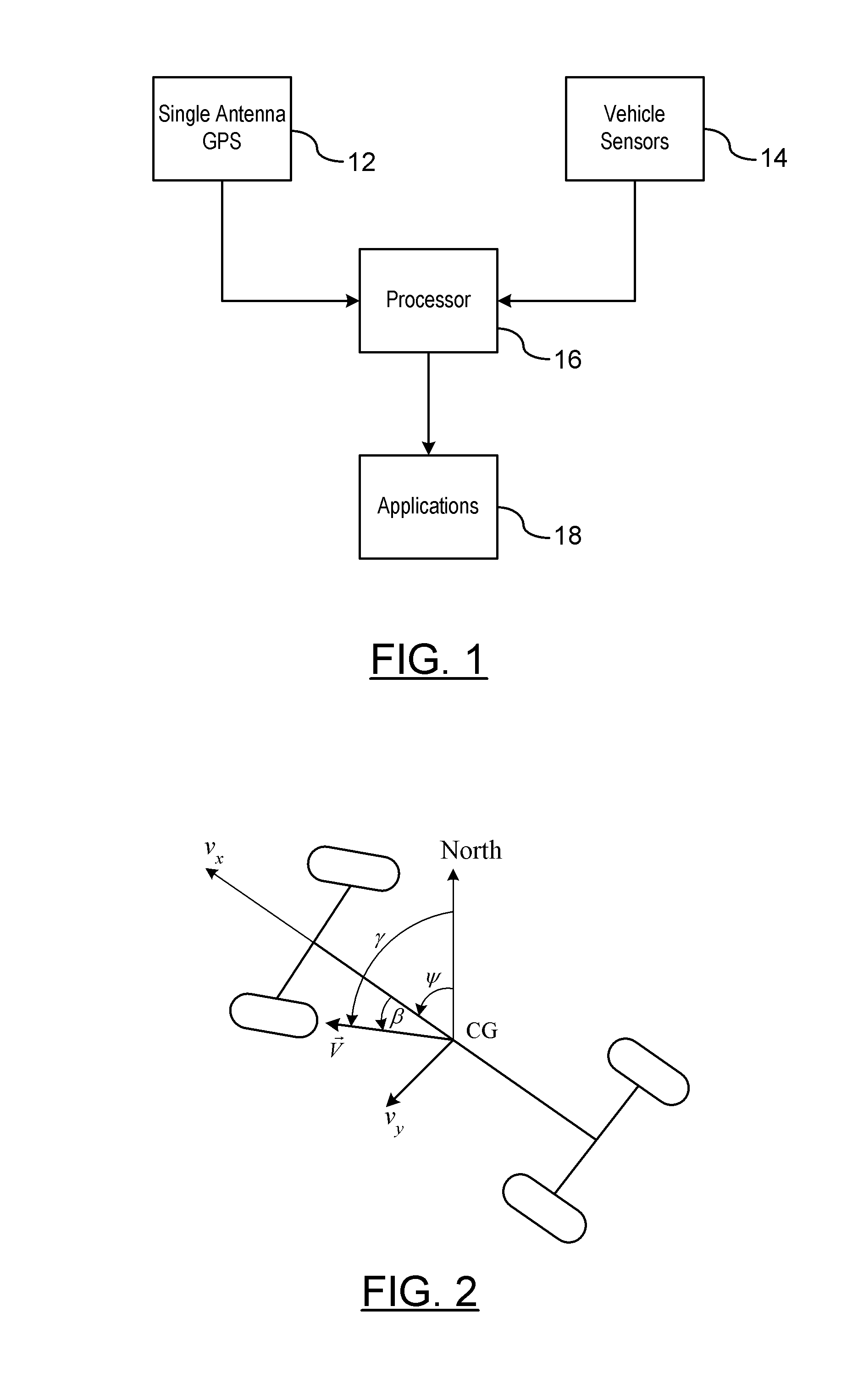
[0009]There is shown in FIG. 1 a system 10 for determining a longitudinal velocity and a lateral velocity of a vehicle. The system includes a single antenna global positioning system (GPS) 12, and at least one sensor 14 that includes, but is not limited to, a yaw rate sensor, accelerometer, and velocity sensor. The system 10 further includes a processor 16 for processing the data received from the single antenna GPS 12 and the at least one sensor 14. The processor 16 determines a longitudinal velocity and a lateral velocity based on the data received by the single antenna GPS 12 and the at least one sensor 14. The longitudinal velocity and lateral velocity obtained from the processor 16 are provided to various vehicle safety and control systems which benefit from knowing an accurate vehicle longitudinal velocity and lateral velocity.

[0010]The single antenna GPS 12 utilizes only one antenna. GPS typically provides a very good velocity measurement that includes a velocity direction (i...


PUM


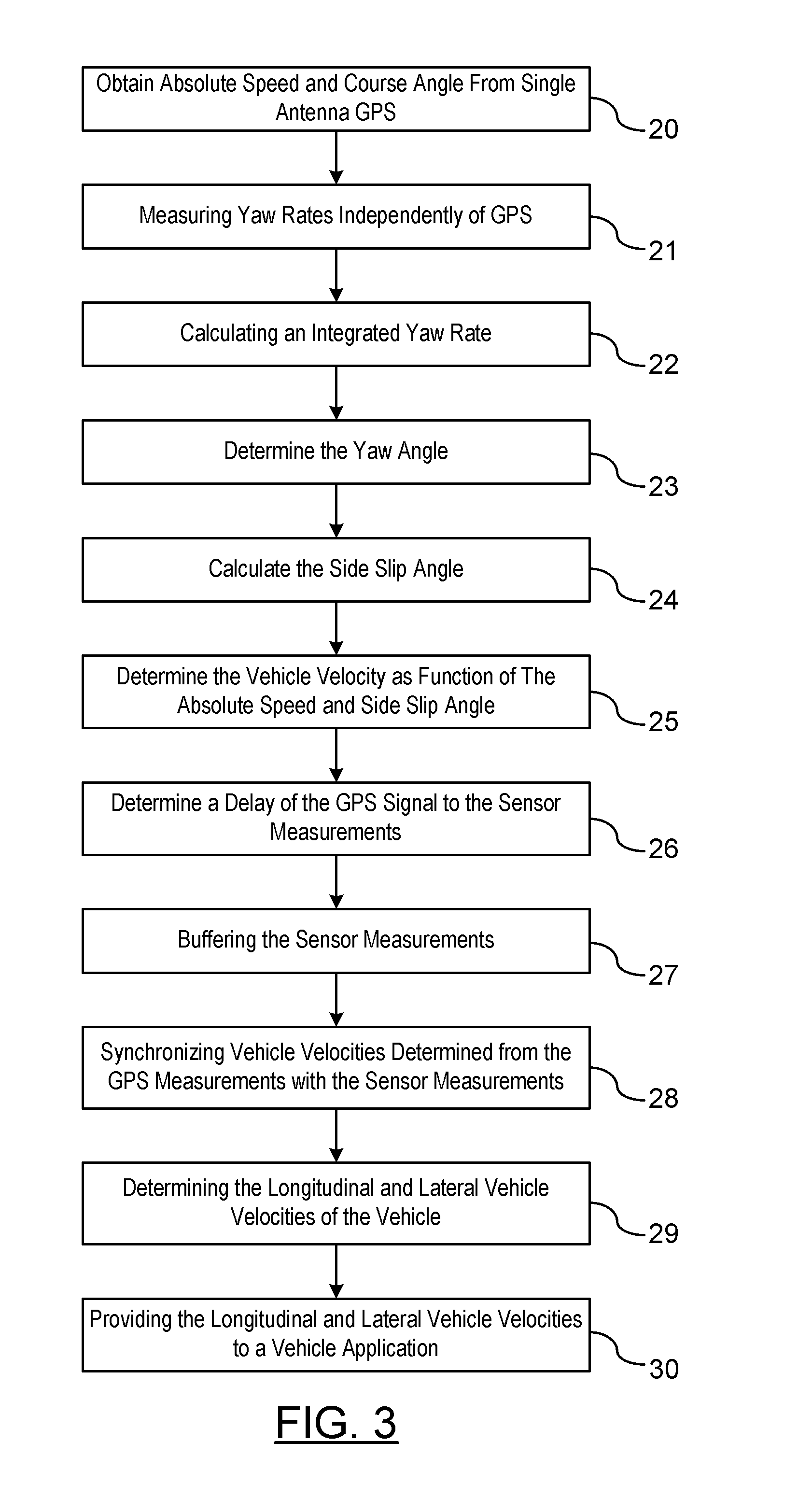
Abstract

A method is provided for estimating vehicle velocity for a vehicle using a single-antenna global positioning system (GPS). An absolute speed and a course angle of the vehicle is measured using the single-antenna GPS. The yaw rates of the vehicle are measured independently of the GPS. An integrated yaw rate of the vehicle is calculated as a function of the measured yaw rates over a period of time. A yaw angle is determined as a function of a reference yaw angle and the integrated yaw rate. Aside slip angle is calculated as a function of the estimated yaw angle and the course angle provided by the GPS. The vehicle velocity is determined as a function of the absolute speed and the side slip angle. The vehicle velocity is provided to a vehicle dynamic control application.

Description

BACKGROUND OF INVENTION[0001]An embodiment relates generally to vehicle velocity estimation.[0002]Various vehicle safety and control systems benefit when utilizing an accurate longitudinal and / or lateral vehicle velocity. Devices for accurately measuring longitudinal and lateral velocity measurements, such as multi-antenna GPS or optical sensors, are either too expensive or externally intrusive. The use of other types of sensors to measure longitudinal and lateral velocity, such as wheel speed sensors or even lateral acceleration sensors, have difficulties in providing accurate measurements when excessive wheel slip is present or when a banked road is present.SUMMARY OF INVENTION[0003]An advantage of an embodiment is estimation of vehicle longitudinal and lateral velocities using single-antenna GPS data which provides greater accuracy than typical sensors utilized on vehicles. The GPS measurement data provides greater accuracy of the course heading angle and absolute speed which is ...

Claims


Application Information

Patent Timeline
IPC IPC(8): G06G7/76G01S19/52
CPCG01S19/52G01C21/165
Inventor O'DEA, KEVIN A.RYU, JIHANNARDI, FLAVIOTAN, HUALIN
Owner GM GLOBAL TECH OPERATIONS LLC
Learn More