Half-wave plate, optical pickup device, polarization conversion element, and projection display device

a technology of polarization conversion element and wave plate, which is applied in the direction of polarising element, record information storage, instruments, etc., can solve the problems of affecting the function affecting the light efficiency of the wave plate, and being exposed in an extremely high temperature environment for a long time. , to achieve the effect of improving conversion efficiency, brighter image and high light efficiency

Active Publication Date: 2011-05-05
SEIKO EPSON CORP
View PDF17 Cites 3 Cited by
  • Summary
  • Abstract
  • Description
  • Claims
  • Application Information

AI Technical Summary

Benefits of technology

[0033]In the polarization conversion element, in another aspect of the invention, the half-wave plate is disposed at a portion of the second principal surface where the first linearly polarized light transmitted through the first optical thin film is emitted or at a portion of the second principal surface where the second linearly polarized light reflected by the second optical thin film is emitted. In another aspect of the invention, the half-wave plate is disposed in the translucent substrate, and arranged so as to be stacked on the exit surface of the first optical thin film where the first linearly polarized light is emitted. In either case, by using the half-wave plate with the conversion efficiency improved as described above, it becomes possible to realize the polarization conversion element having extremely high light efficiency in the band broader than in the related art.
[0034]Further, according to still another aspect of the invention, there is provided a projection display device including alight source, the polarization conversion element according to the above aspect of the invention adapted to convert the light from the light source into the second linearly polarized light and emit the second linearly polarized light, a modulation section adapted to modulate the second linearly polarized light emitted from the polarization conversion element in accordance with image information to be projected, and a projection optical system adapted to project the light modulated by the modulation section. Similarly, by using the half-wave plate with the conversion efficiency improved compared to the related art as described above, a brighter image can be obtained with the light source of the same output, or an image with a comparable brightness can be obtained when reducing the output of the light source, therefore, the power consumption can be reduced.

Problems solved by technology

Therefore, the materials absorb the blue-violet laser to generate heat, and might cause deterioration of the materials themselves to hinder the function of the wave plate.
Further, in optical disc recording / reproduction devices compliant with the Blu-ray standard, the half-wave plate is disposed adjacent to the laser source of each of the optical pickup devices, and is exposed in an extremely high temperature environment for a long period of time.
However, in the half-wave plate formed of a quartz crystal single plate, the design method considering the variation in the polarization state due to the rotation of the polarization plane caused by the rotatory power in addition to the variation in the polarization state due to the phase difference caused by the birefringent property has not ever been reported as far as at least the inventors know.
Therefore, there arises a problem that if the design phase difference of the quartz crystal half-wave plate is set to 180°, the conversion efficiency does not necessarily become 100% depending on the cutting angle of the quartz crystal plate.
Therefore, the conversion efficiency of the quartz crystal wave plate is degraded.
Therefore, since the strength of the quartz crystal plate is remarkably degraded to make the quartz crystal plate easy to be broken, handling in manufacturing processes and in use is extremely difficult.
Further, the blue-violet lasers cause a problem that wavelength of the oscillated laser drifts (varies) when generating high heat and expanding in use.
Therefore, in the case of using the blue-violet lasers in the light sources of the optical pickup devices, there arises in the half-wave plate a problem that the conversion efficiency of the linearly polarized light is deteriorated due to the wavelength drift of the incident laser beam.
In particular, since the half-wave plate in a higher-order mode has a large thickness, an amount of the variation thereof increases as the phase difference increases, and the conversion efficiency is more significantly deteriorated.

Method used


Image

  • Half-wave plate, optical pickup device, polarization conversion element, and projection display device
  • Half-wave plate, optical pickup device, polarization conversion element, and projection display device
  • Half-wave plate, optical pickup device, polarization conversion element, and projection display device

Examples


Embodiment Construction

[0048]Hereinafter, some preferred embodiments of the invention will be described in detail with reference to the accompanying drawings.

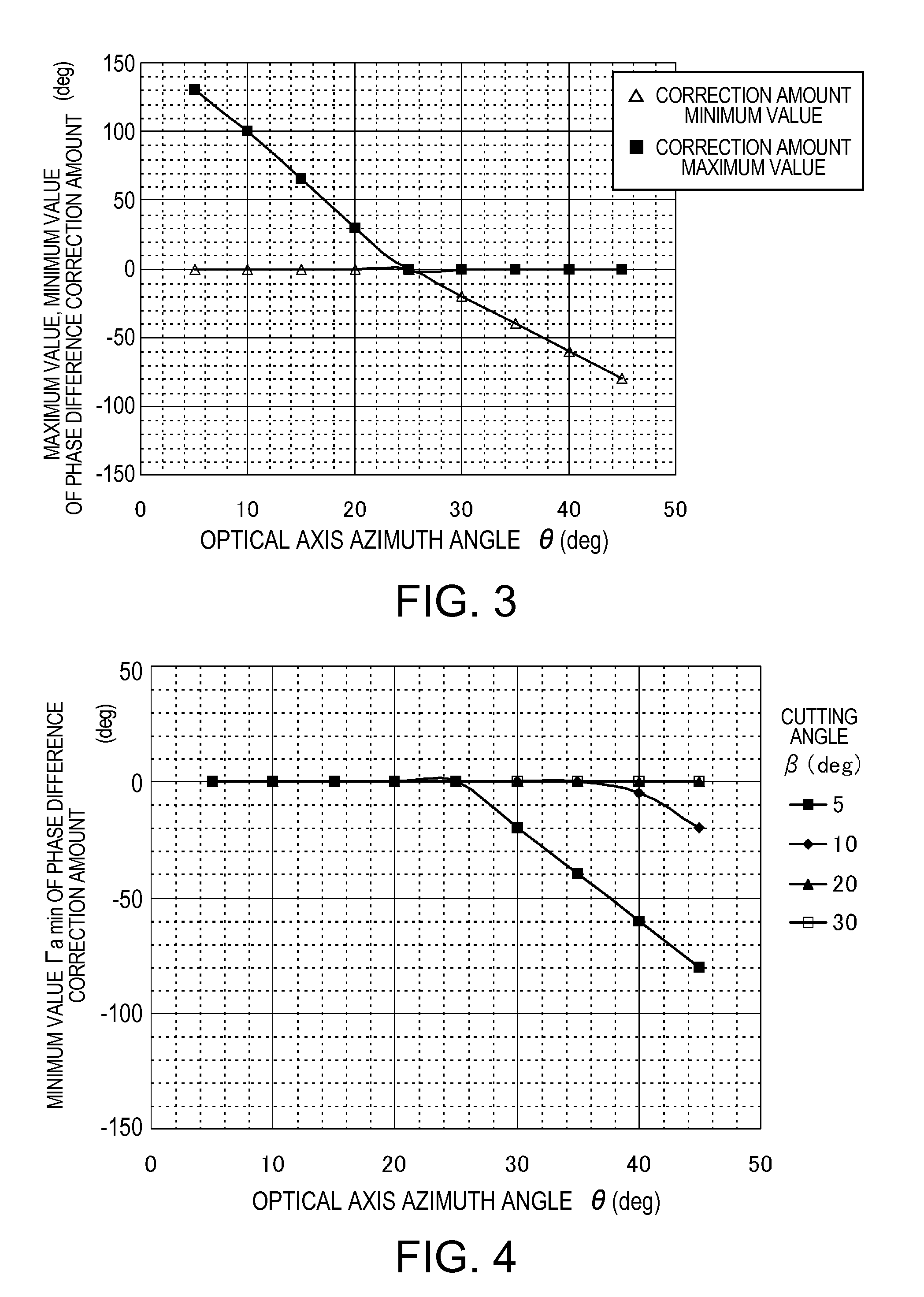
[0049]FIGS. 6A and 6B schematically show a half-wave plate according to the embodiment of the invention. The half-wave plate 1 of the present embodiment is formed of a single quartz crystal wave plate with a constant thickness. As shown in FIG. 6C, the quartz crystal wave plate is carved out to be a quartz crystal plate having a cutting angle β defined by the normal line provided to the entrance surface 1a (or the exit surface 1b) and the crystal optical axis (the Z-axis) in a range of 5°≦β≦30°. In particular, by setting the cutting angle within this range, the quartz crystal wave plate having the thickness with which the plate has sufficient strength for preventing working and handling in manufacturing from becoming difficult as the single-plate half-wave plate can be processed.

[0050]The phase difference Γ of the half-wave plate 1 can be expressed a...


PUM

PropertyMeasurementUnit
angleaaaaaaaaaa
thicknessaaaaaaaaaa
birefringent propertyaaaaaaaaaa

Abstract

A half-wave plate includes a single crystal plate made of an inorganic material having a birefringent property and rotatory power, wherein a polarization plane of linearly polarized light entering from an entrance surface of the crystal plate is rotated and then output from an exit surface of the crystal plate.

Description

BACKGROUND[0001]1. Technical Field[0002]The present invention relates to a half-wave plate made in particular of an inorganic crystalline material having a birefringent property and rotatory power such as quartz crystal. Further, the invention relates to an optical pickup device, a polarization conversion element, and a projection display device using the half-wave plate.[0003]2. Related Art[0004]In the past, half-wave plates for outputting outgoing light, which is linearly polarized light having a polarization plane obtained by rotating the polarization plane of linearly polarized light as the incident light by predetermined angle, for example, 90°, have been used in optical devices such as optical pickup devices used for recording / reproduction in optical disk drives, polarization conversion elements, or projection display devices such as liquid crystal projectors. In general, as a material of the wave plate, there are used a resin film made of an organic material such as polycarbo...

Claims


Application Information

Patent Timeline
Patent Type & Authority Applications(United States)
IPC IPC(8): G03B21/14G02B5/30G11B7/00
CPCG02B5/3016G02B5/3083G11B7/1369G03B33/12G11B7/1365G03B21/14G03B21/2073
Inventor OTO, MASAYUKI
Owner SEIKO EPSON CORP
Why Eureka
Try Eureka