Eureka AIR delivers breakthrough ideas for toughest innovation challenges, trusted by R&D personnel around the world.

Fan control system

a control system and fan technology, applied in the direction of motor/generator/converter stopper, dynamo-electric converter control, instruments, etc., can solve the problems of wasting power and consuming a lot of power of the fan used to dissipate hea

Inactive Publication Date: 2011-05-05
HONG FU JIN PRECISION IND (SHENZHEN) CO LTD +1
View PDF11 Cites 13 Cited by
  • Summary
  • Abstract
  • Description
  • Claims
  • Application Information

AI Technical Summary

Problems solved by technology

Fans used to dissipate heat can consume a lot of power and even waste power if they are operating faster than needed.

Method used


Image

  • Fan control system
  • Fan control system
  • Fan control system

Examples


Embodiment Construction

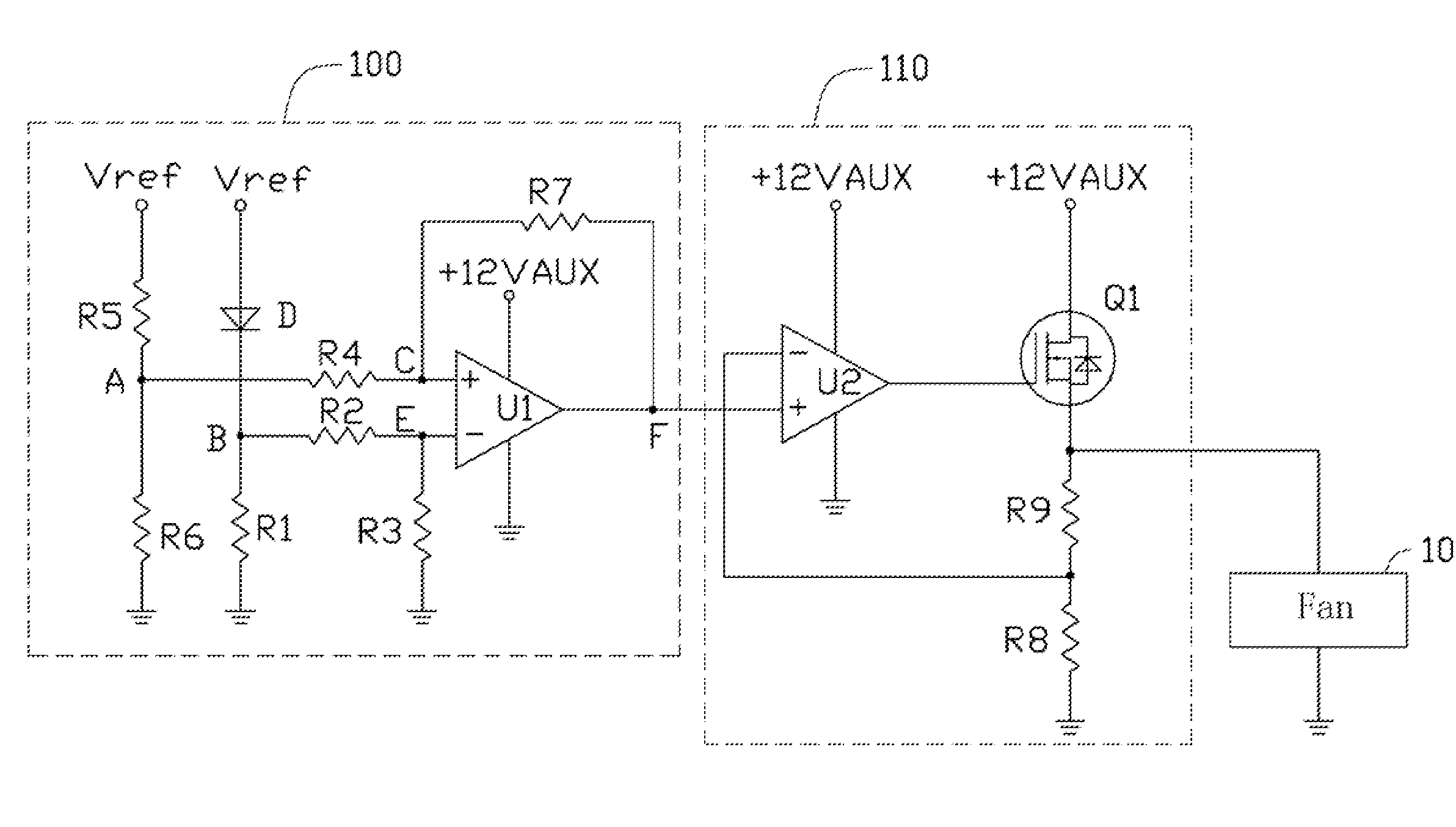
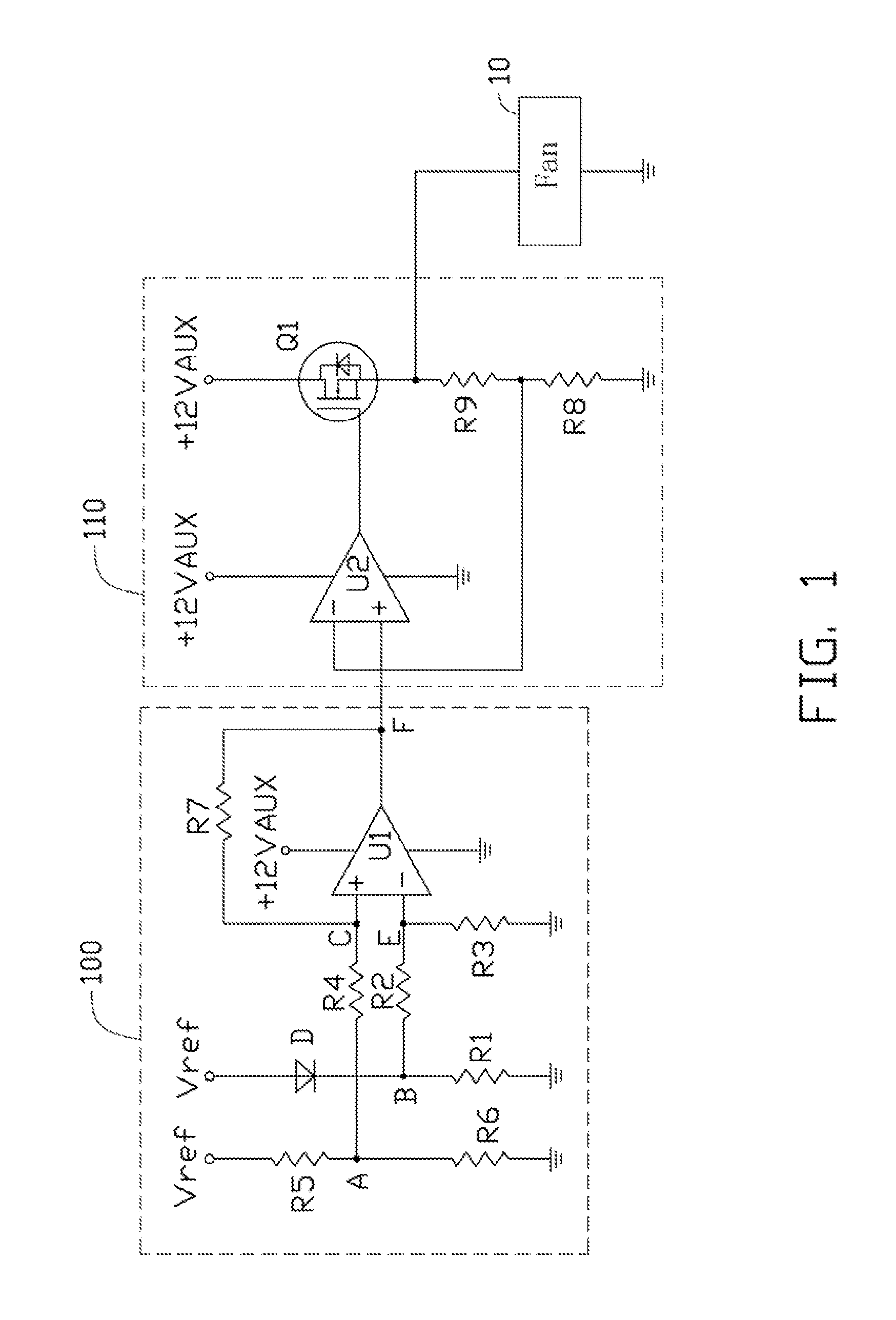
[0007]Referring to FIG. 1, a first embodiment of a fan control system for controlling a rotation rate of a fan 10 of an electronic device includes a temperature detecting circuit 100 and a rotation rate control circuit 110.

[0008]The detecting circuit 100 is allocated to detect temperature in an enclosure housing the fan 10 of the electronic device, and convert the temperature to a voltage signal. The control circuit 110 receives the voltage signal from the detecting circuit 100, and controls the rotation rate of the fan 10 according to the voltage signal.

[0009]The detecting circuit 100 includes a thermal diode D, an amplifier U1, and resistors R1-R7. An anode of the thermal diode D is connected to a reference power Vref. A cathode of the thermal diode D is grounded via the resistor R1, and connected to an inverting terminal of the amplifier U1 via the resistor R2. The inverting terminal of the amplifier U1 is grounded via the resistor R3. A non-inverting terminal of the amplifier U1...


PUM


Abstract

A fan control system includes a temperature detecting circuit and a rotation rate control circuit. The detecting circuit includes an amplifier and a thermal diode. The detecting circuit detects temperature and outputs a voltage signal. The control circuit receives the voltage signal and controls the rotation rate of the fan according to the voltage signal.

Description

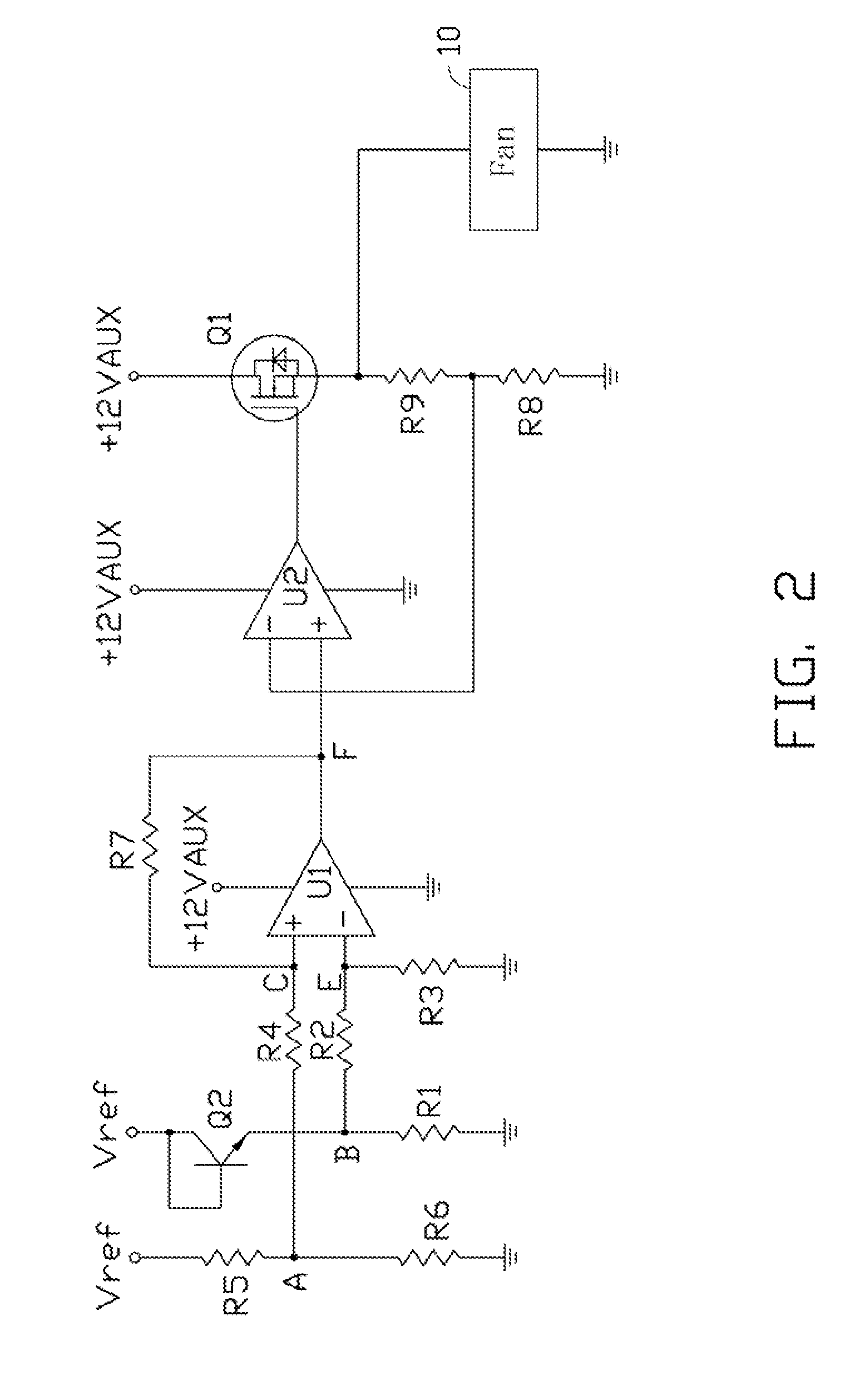
BACKGROUND[0001]1. Technical Field[0002]The present disclosure relates to a control system for a fan.[0003]2. Description of Related Art[0004]With advancements in computer technology, greater demands have been being seen for more power as well as for conserving power. Fans used to dissipate heat can consume a lot of power and even waste power if they are operating faster than needed. Therefore, precise control over fan speed to conserve energy meanwhile ensuring proper heat dissipation is desired.BRIEF DESCRIPTION OF THE DRAWINGS[0005]FIG. 1 is a circuit diagram of a first embodiment of a fan control system.[0006]FIG. 2 is a circuit diagram of a second embodiment of a fan control system.DETAILED DESCRIPTION[0007]Referring to FIG. 1, a first embodiment of a fan control system for controlling a rotation rate of a fan 10 of an electronic device includes a temperature detecting circuit 100 and a rotation rate control circuit 110.[0008]The detecting circuit 100 is allocated to detect tem...

Claims


Application Information

Patent Timeline
IPC IPC(8): G05D23/00
CPCF04D27/004Y02B30/70
Inventor HUANG, YONG-ZHAO
Owner HONG FU JIN PRECISION IND (SHENZHEN) CO LTD
Why Eureka
Eureka Blog
Learn More