
System and method for hardware acceleration of a software transactional memory

a hardware acceleration and transactional memory technology, applied in the field of transactional memory, can solve the problems of significant policy embedding in silicon, data versioning and validation overhead, etc., and achieve the effects of improving the performance of common-case bounded transactions, good scalability, and easy implementation efficiency

Inactive Publication Date: 2011-04-28
UNIVERSITY OF ROCHESTER
View PDF5 Cites 55 Cited by
  • Summary
  • Abstract
  • Description
  • Claims
  • Application Information

AI Technical Summary

Benefits of technology

[0009]It is another object of the invention to reduce the overhead relative to existing software TM proposals.
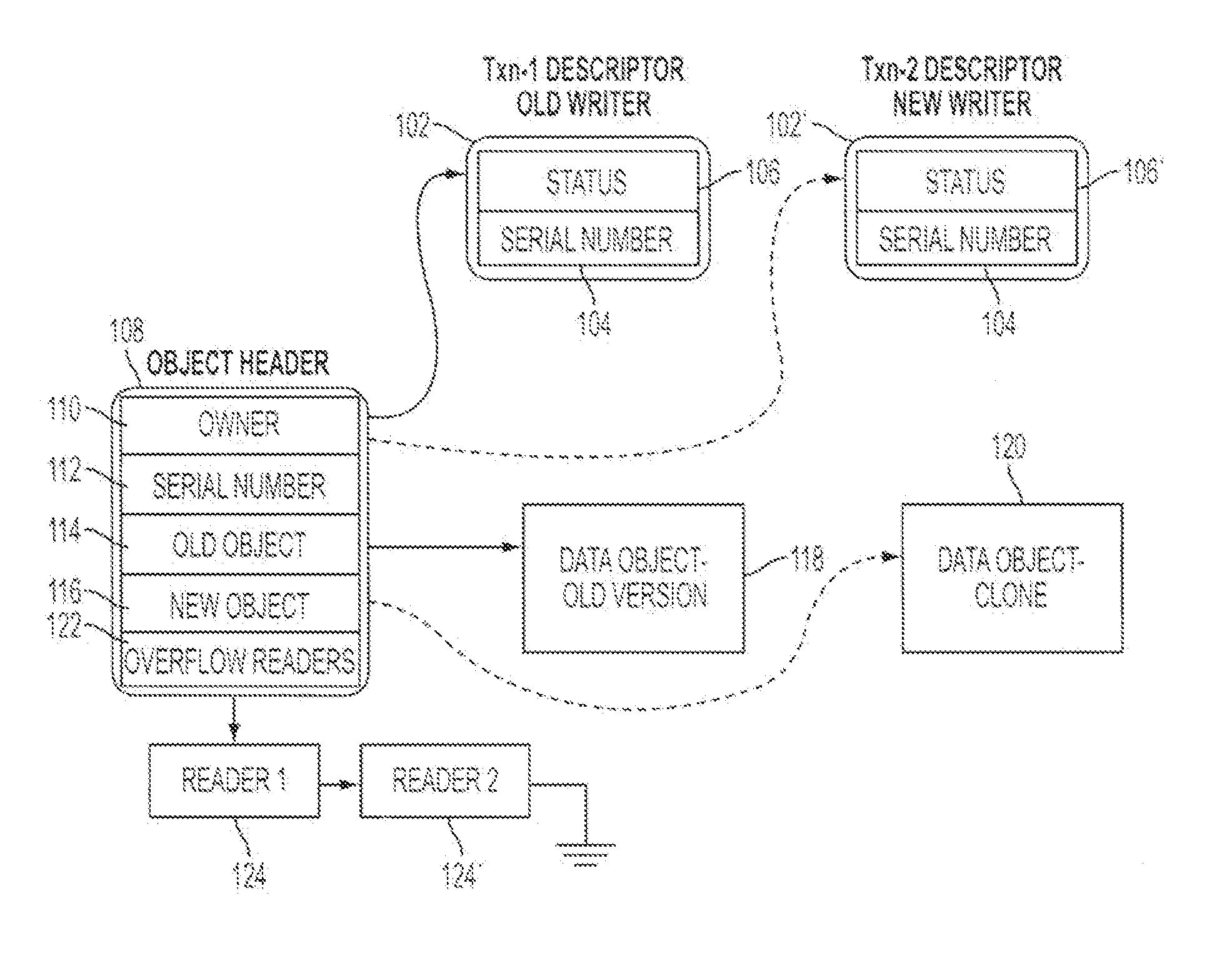
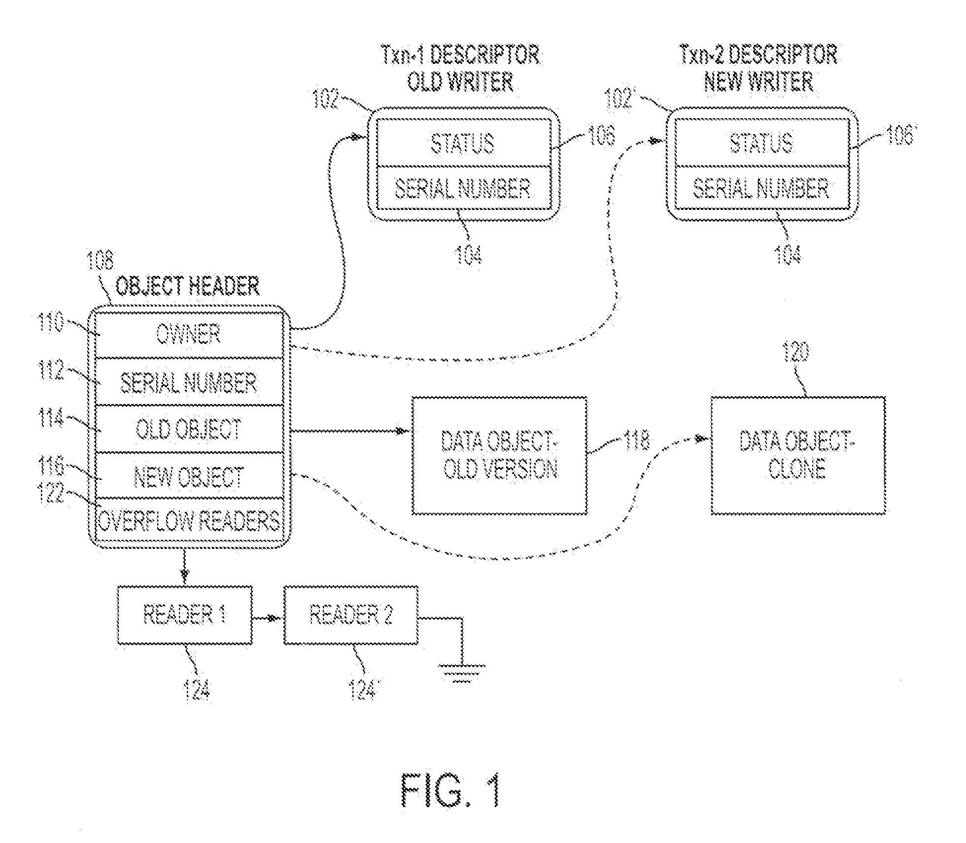
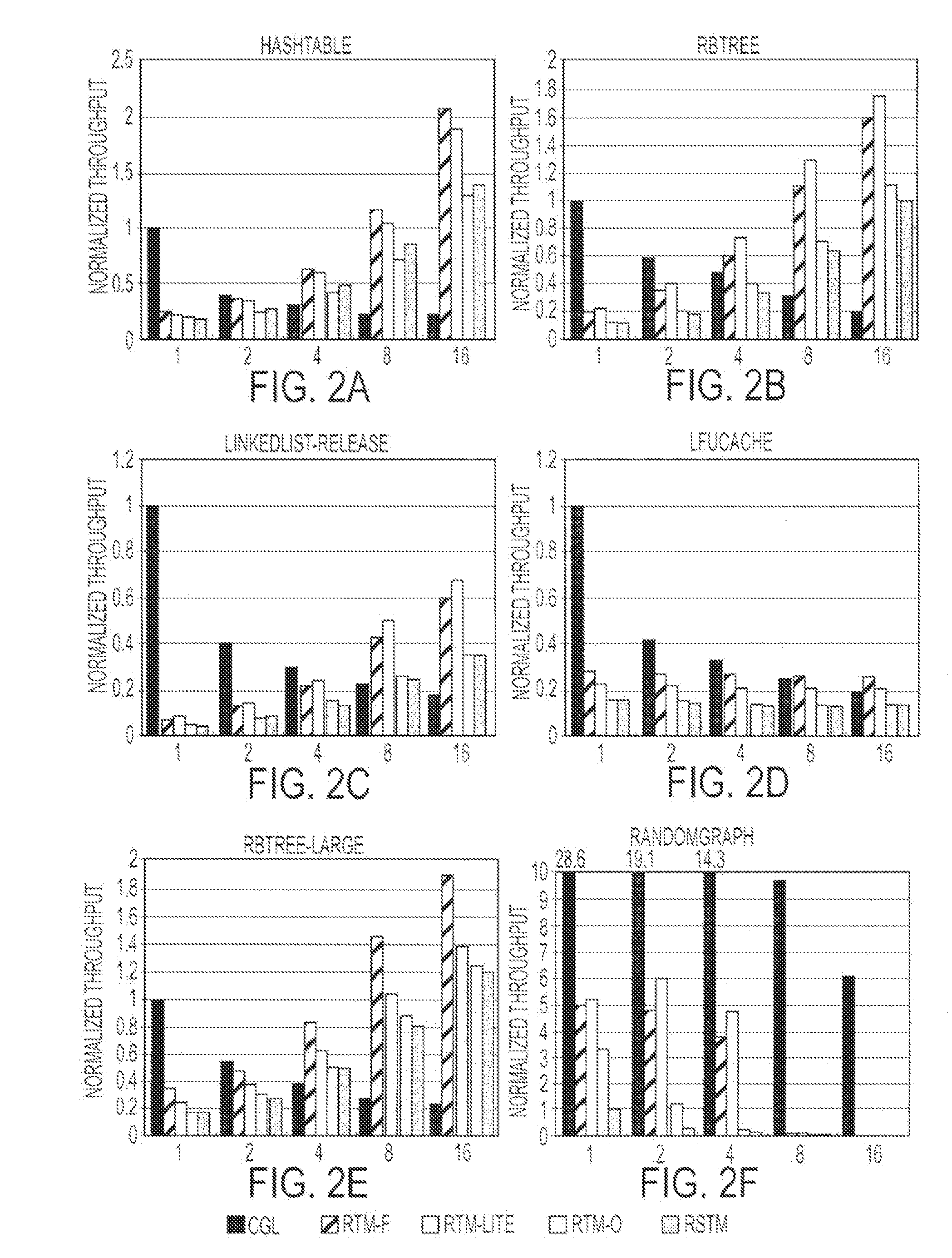
[0017]RTM-Lite, a simpler embodiment that relies on alert-on-update but not programmable data isolation, is effective at eliminating validation overhead, but loses to RTM for transactions that modify large objects. When transactions overflow the available hardware support, performance degrades linearly from that of the all fast-path mode to that of the all overflow mode, based on the fraction of overflowed transactions. Detecting conflicts eagerly (on first access) or lazily (at commit time), enabled by the multiple-writer protocol, can result in differences in performance in either direction depending on the application access pattern (up to two orders of magnitude for one workload), demonstrating the need for policy flexibility.

Problems solved by technology

Pure hardware TM proposals have the advantage of speed, but are typically highly ambitious and embed significant amounts of policy in silicon.
Software TM proposals run on stock processors and provide substantial flexibility in policy, but incur significant overhead for data versioning and validation in the face of conflicting transactions.
Unfortunately, this system still embeds significant policy in silicon.

Method used


Image

  • System and method for hardware acceleration of a software transactional memory
  • System and method for hardware acceleration of a software transactional memory
  • System and method for hardware acceleration of a software transactional memory

Examples


Embodiment Construction

[0029]A preferred embodiment of the present invention will be set forth in detail with reference to the drawings, in which like reference numerals refer to like elements or steps throughout.

[0030]We will first describe our hardware mechanisms in detail, including instruction set extensions, coherence protocol, and the mechanism used to detect conflicts and abort remote transactions. We will then describe the RTM runtime that leverages this hardware support. We will then evaluate the performance of RTM in comparison to coarse-grain locks, an all-software TM system, and an “RTM-Lite” system that uses alert-on-update but not programmable data isolation. We will also present results to demonstrate the benefits of policy flexibility.

[0031]In terms of hardware support, transactional memory has two principal requirements: the ability to detect when transactions in different threads conflict, and the ability to hide a transaction's updates from other threads until the transaction commits. T...


PUM


Abstract

In a transactional memory technique, hardware serves simply to optimize the performance of transactions that are controlled fundamentally by software. The hardware support reduces the overhead of common TM tasks—conflict detection, validation, and data isolation—for common-case bounded transactions. Software control preserves policy flexibility and supports transactions unbounded in space and in time. The hardware includes 1) an alert-on-update mechanism for fast software-controlled conflict detection; and 2) programmable data isolation, allowing potentially conflicting readers and writers to proceed concurrently under software control.

Description

REFERENCE TO RELATED APPLICATION [0001]The present application claims the benefit of U.S. Provisional Patent Application No. 60 / 748,585, filed Dec. 9, 2005, whose disclosure is hereby incorporated by reference in its entirety into the present disclosure.STATEMENT OF GOVERNMENT INTEREST[0002]The work leading to the present invention was supported in part by NSF grants CCR-0204344, CNS-0411127, CNS-0615139, and CNS-0509270. The government has certain rights in the invention.FIELD OF THE INVENTION [0003]The present invention relates to transactional memory and more particularly to an integrated hardware-software approach to flexible transactional memory.DESCRIPTION OF RELATED ART [0004]Explicitly parallel hardware, once confined to high-end servers and scientific computing, will soon dominate the full computing spectrum. As a result of increasing chip density coupled with power limitations, multicore chips—often chip multiprocessors (CMPs) of simultaneous multithreaded cores (SMTs)—are...

Claims


Application Information

Patent Timeline
IPC IPC(8): G06F12/08
CPCG06F12/0842
Inventor SCOTT, MICHAEL L.DWARKADAS, SANDHYASHRIRAMAN, ARRVINDHMARATHE, VIRENDRASPEAR, MICHAEL F.
Owner UNIVERSITY OF ROCHESTER
Learn More