
Ultrasonic tip for sinus membrane elevation

a technology of ultrasonic tip and sinus membrane, which is applied in the field of ultrasonic tip for sinus membrane elevation, can solve the problems of reducing the safety reducing not always having a sufficient thickness or volume of cortical bone for the stable elevation of the maxilla, etc., so as to reduce the risk of tearing the membrane, reduce the risk of tearing the latter, and ensure the effect of lifting the sinus membran

Inactive Publication Date: 2011-04-28
SOC POUR LA CONCEPTION DES APPL DES TECHN ELECTRONIQUES SATELEC
View PDF6 Cites 7 Cited by
  • Summary
  • Abstract
  • Description
  • Claims
  • Application Information

AI Technical Summary

Benefits of technology

"The present invention proposes a new instrument designed to lift the sinus membrane without tearing it. This is achieved by using an ultrasonic tip with a flat surface that reduces the risk of tearing the membrane. The tip has an internal irrigation channel that allows for the introduction of fluid under the membrane and the use of ultrasound vibrations to cause the membrane to detach and elevate it. The flat surface of the tip also allows for the introduction of a larger amount of fluid and facilitates the use of a ring-shaped part to induce cavitation. The instrument can be used in an ultrasonic dental surgery device that includes a handpiece and an irrigation fluid distributor. The method involves drilling a hole in the maxilla and introducing the ultrasonic tip while setting up ultrasound vibrations and feeding the inner irrigation channel of the tip with irrigation fluid."

Problems solved by technology

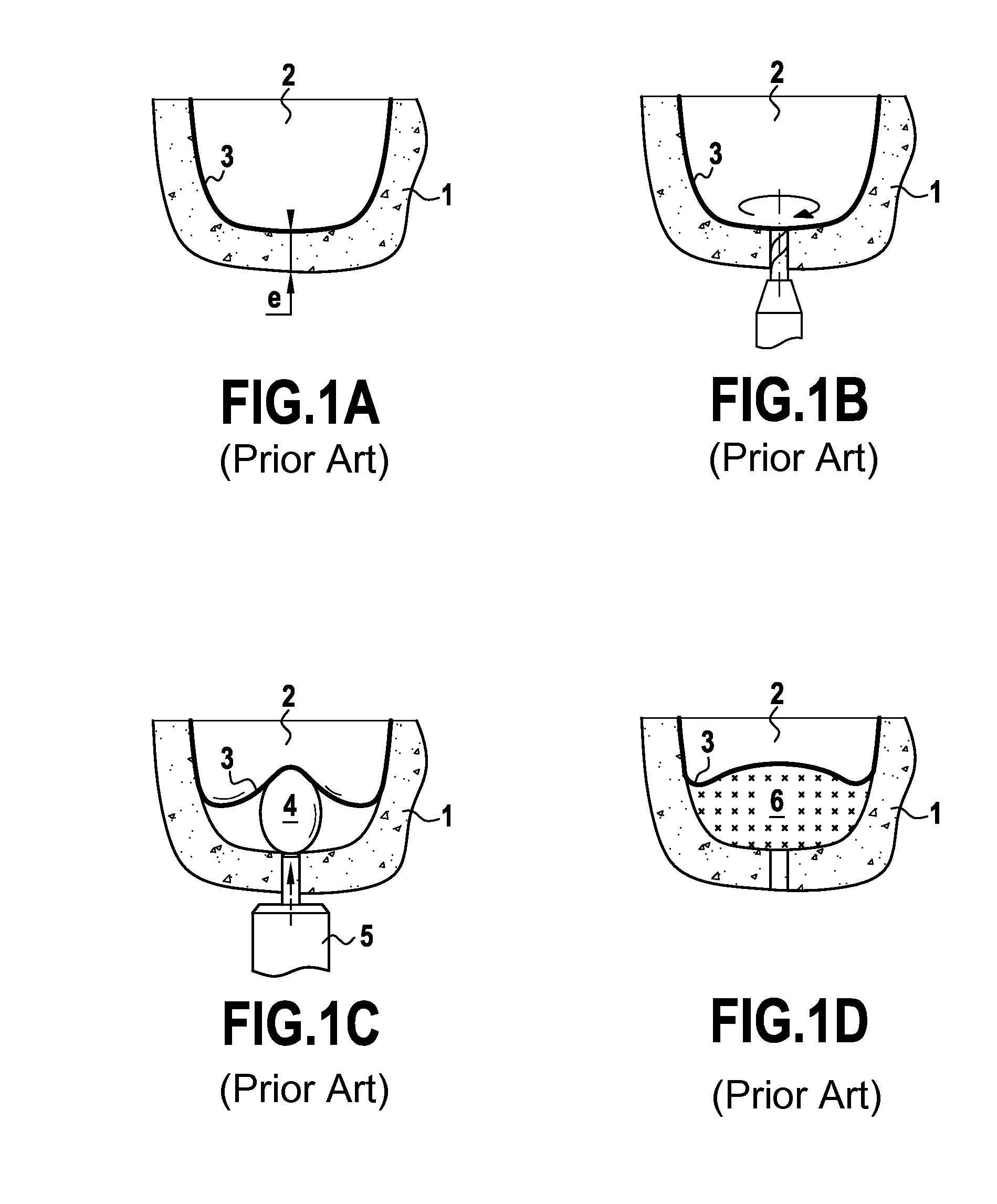
However, the maxilla does not always have a sufficient thickness or volume of cortical bone for the stable placement of dental implants.
Elevation of the sinus membrane is a very delicate operation as it is very fragile and may be torn at any time by the instrument used in direct contact with it.
Such a tearing seriously compromises the success of implantation in particular because of the dispersion of the bone substance in the sinus and the incurred risks of infection.
Instruments currently used to lift the membrane, even those using a balloon, are in contact with only a very small area of the membrane so that the latter may be easily torn when the physician applies too strong a pressure with the instrument.
It is all the more difficult for the physician to control the pressure exerted on the membrane because of the poor visibility of the site and the depth of the approach.
Moreover, certain instruments may be too invasive.

Method used


Image

  • Ultrasonic tip for sinus membrane elevation
  • Ultrasonic tip for sinus membrane elevation
  • Ultrasonic tip for sinus membrane elevation

Examples


Embodiment Construction

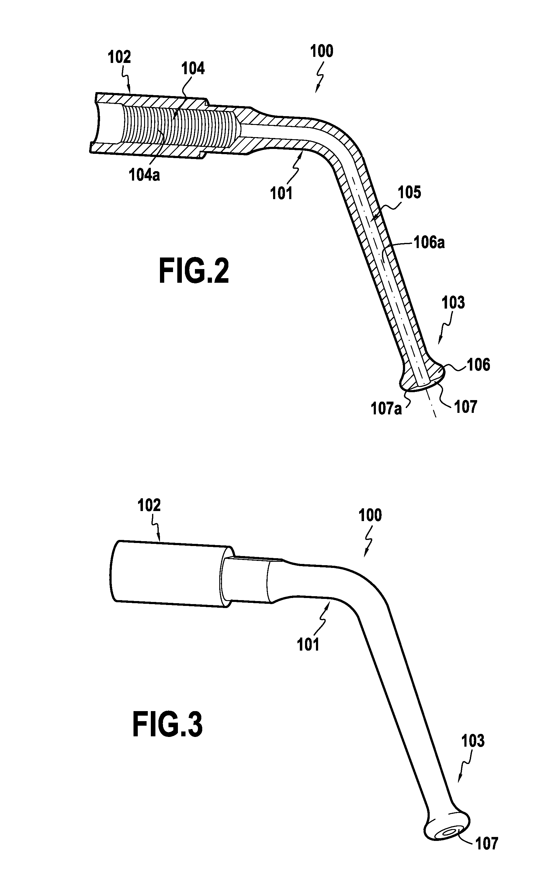
[0025]FIGS. 2 and 3 show an ultrasound tip 100 used to lift the sinus membrane according to an embodiment of the present invention.

[0026]Ultrasound tip 100 is formed of a body 101, for example in a metallic material, extending between a proximal part 102 intended to be mechanically coupled to a surgical handpiece generating vibrations as explained below and a distal part 103 intended to reproduce the vibrations transmitted by the handpiece. The proximal part 102, extending along a longitudinal axis (101a), comprises a cavity 104, the walls of which are threaded 104a to allow the tip to be attached to the handpiece. The cavity 104 continues in an internal irrigation channel 105 which extends inside body 101 for all its length and emerges at the end of the distal part 103.

[0027]The distal part 103 of tip 100 extends along a longitudinal axis 101b. The distal parts 103 corresponds to the part of the tip which is introduced into the mouth of the patient for reaching the hole drilled in ...


PUM


Abstract

Method for lifting a sinus membrane located between a sinus and a maxilla that involves the drilling of a hole of a given diameter in the maxilla reaching the sinus membrane, and includes introducing in the hole an ultrasonic tip having a distal part including a ring-shaped part of increasing cross-section and a distal end formed by a flat area extending generally perpendicular to the longitudinal axis of the distal part. The flat area of the distal part has a distal side facing away from the proximal part and is bordered by a rounding, the ring shaped part being larger than the body of the tip but closely corresponding to the diameter of the hole. The tip includes an internal irrigation channel emerging on the distal side of the flat area. While the tip is within the hole, the tip is advanced towards the membrane while ultrasound vibrations are fed to the tip and irrigation fluid is supplied to the internal irrigation channel. This creates a cavitation effect in the irrigation fluid between the tip and the membrane and a lifting force that gently detaches and elevates the sinus membrane without requiring a direct contact between the membrane and the distal part of the tip.

Description

RELATED APPLICATION DATA[0001]This application is a divisional of application Ser. No. 11 / 822,760 filed Jul. 10, 2007, the entirety of which is incorporated herein by reference.BACKGROUND TO THE INVENTION[0002]The present invention concerns the field of dental implants and in particular devices used to prepare the implantation site in odontology.[0003]For long-term integration in the maxillary bone (osteointegration), the implant must be fixed in a sufficient volume of cortical bone. However, the maxilla does not always have a sufficient thickness or volume of cortical bone for the stable placement of dental implants. In this case, the bone mass must be augmented on the sinus side of the maxilla. The bone graft may come from the patient himself (autogenous bone graft) or from an external source (artificial bone graft).[0004]FIGS. 1A to 1D show the various stages implemented during a maxillary bone augmentation procedure on a patient's upper jaw. FIG. 1A represents a maxilla 1 delimi...

Claims


Application Information

Patent Timeline
Patent Type & Authority Applications(United States)
IPC IPC(8): A61B17/16
CPCA61B17/1688A61B2017/32032A61C8/0092A61C8/0006A61C3/03A61C17/20
Inventor KURREK, ANDREASWAINWRIGHT, MARCEL A.TROEDHAN, ANGELODIERAS, FRANCIS
Owner SOC POUR LA CONCEPTION DES APPL DES TECHN ELECTRONIQUES SATELEC
Learn More