
Method and System for Providing an Emergency Location Service

a technology for emergency location and service, applied in the field can solve the problems of processing procedures of emergency location service, and the different services provided by known ims do not disclose emergency location service details, and achieve the effect of efficiently providing emergency location service and rapid provision of emergency location servi

Inactive Publication Date: 2011-04-28
LG ELECTRONICS INC
View PDF5 Cites 63 Cited by
  • Summary
  • Abstract
  • Description
  • Claims
  • Application Information

AI Technical Summary

Benefits of technology

The present invention relates to an emergency location service using an IP multimedia subsystem (IMS) core. The technical effect of the invention is to provide a method and system for providing an emergency location service using an IMS core, regardless of the structure of the network or system providing the location service. This allows for a faster processing of emergency call initiation requests and ensures usefulness of accessory services. The invention also includes a method for transmitting an emergency call initiating request message to an emergency center and acquiring current location information of the user equipment. The current location information can be used to establish an emergency call with the emergency center.

Problems solved by technology

However, various services provided from the known IMS do not disclose details of the emergency location service.
In addition, since message processing procedures and transmission parameters between entities in the networks or systems for providing the emergency location service are different from each other depending on structures of the networks, there is a problem that the processing procedures of the emergency location service to be provided by the networks or systems should be prescribed different depending on the structures of the networks.

Method used


Image

  • Method and System for Providing an Emergency Location Service
  • Method and System for Providing an Emergency Location Service
  • Method and System for Providing an Emergency Location Service

Examples


first embodiment

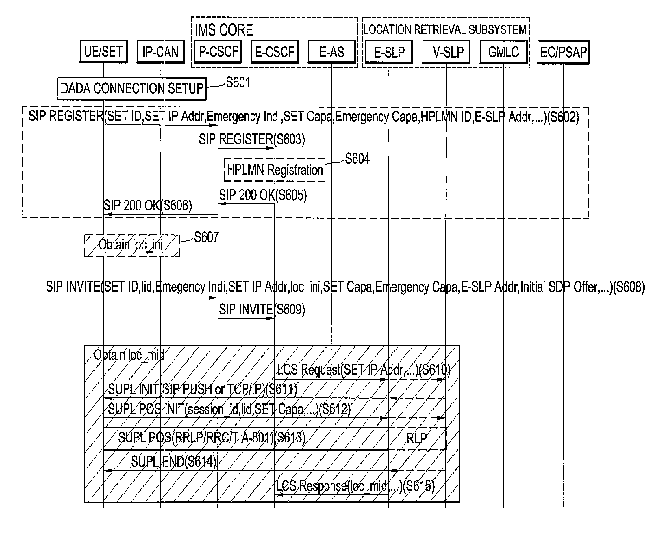
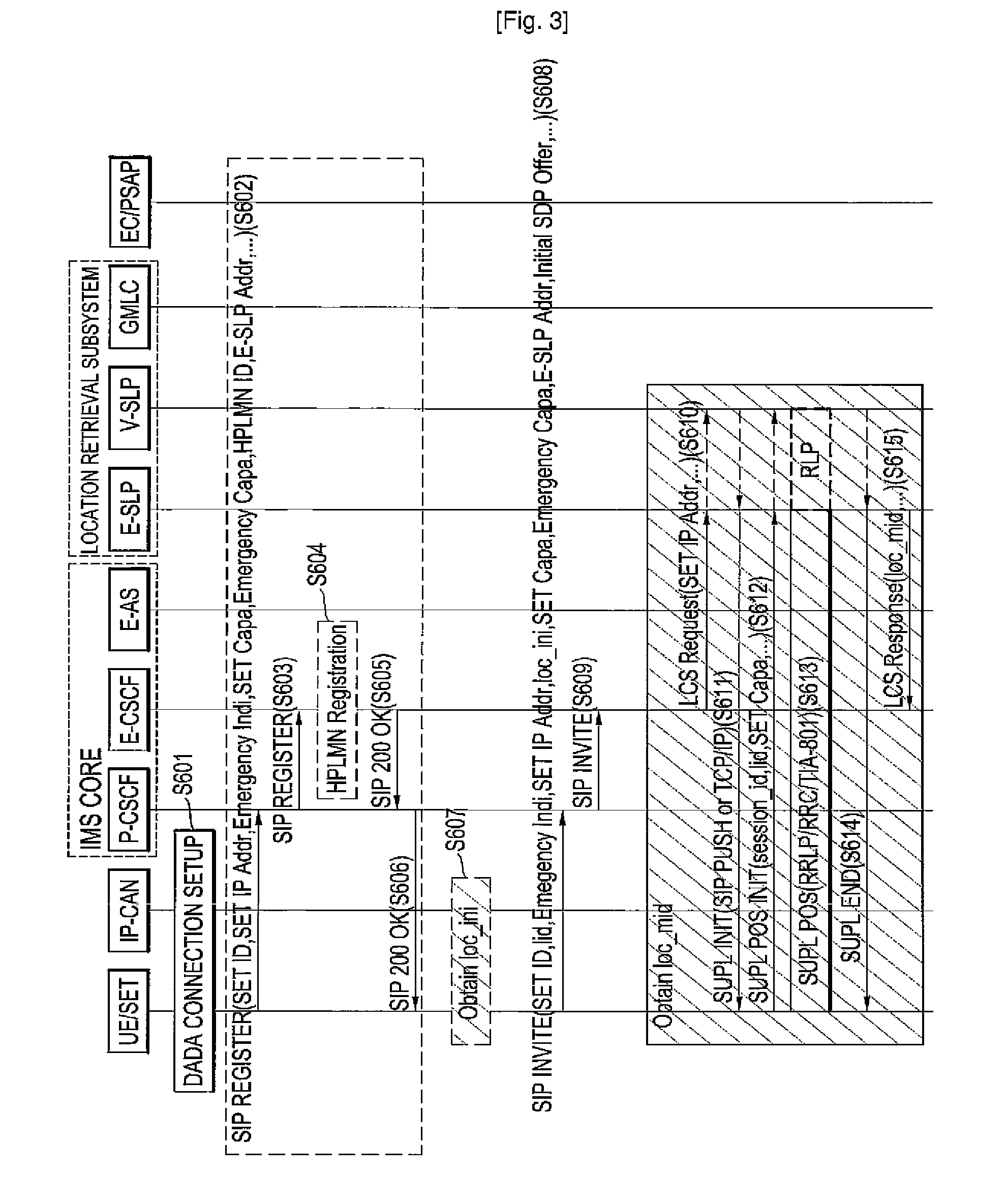
[0058]FIGS. 3 and 4 are flowcharts of messages illustrating first and second halves of steps in the method for providing an emergency location service according to a first embodiment of the invention, where an intermediate medium for processing the IMS signal and the LCS signal is the E-CSCF. As shown in FIGS. 3 and 4, location information of the SET including a location value of the SET is classified into three kinds of initial location information, mid-call (or current) location information, and updated location information.

[0059]First, the initial location information includes an initial location value (loc_ini) acquired through interoperation of the SET with the IP-CAN and is, for example, information included in an emergency call initiating request message transmitted to the IMS core from the user equipment. The loc_ini included in the initial location information may include a cell IP of the IP-CAN or an access point ID in addition to a physical location value. The loc_ini may...

second embodiment

[0133]Next, a method for providing an emergency location service according to a second embodiment of the invention will be described.

[0134]FIGS. 5 and 6 are flowcharts of messages illustrating a procedure of providing an emergency location service according to the second embodiment of the invention. The second embodiment is different from the first embodiment in which the intermediate medium is the E-CSCF, in that the intermediate medium processing the IMS signal and the LCS signal is the E-AS. That is, in the second embodiment, an entity taking charge of the exchange of messages between the IMS core and the location retrieval subsystem is the E-AS. As shown in FIGS. 5 and 6, the location information of the SET including the location value of the SET is classified into the initial location information, the mid-call location information, and the updated location information.

[0135]Similarly to the first embodiment, the initial location information includes an initial location value (l...

third embodiment

[0155]Next, a method for providing an emergency location service according to a third embodiment of the invention will be described.

[0156]FIGS. 7 and 8 are flowcharts of messages illustrating a procedure of providing an emergency location service according to the third embodiment of the invention. The third embodiment is equal to the second embodiment, in that the intermediate medium processing the IMS signal and the LCS signal is the E-AS. However, the third embodiment is different from the second embodiment but equal to the first embodiment, in that an entity of the IMS core communicating with an emergency center is the E-CSCF. As shown in FIGS. 7 and 8, the location information of the SET including the location value of the SET is classified into the initial location information, the mid-call location information, and the updated location information.

[0157]Similarly to the first and second embodiments, the initial location information includes an initial location value (loc_ini) ...


PUM


Abstract

Provided are a method and a system for providing an emergency location service using an IMS core. In the method, when the IMS core receives an emergency call initiating request message from a user equipment, the IMS core transmits a location service request message requesting for retrieving a location of the user equipment to a location retrieval subsystem in response to the emergency call initiating request message. Then, when the IMS core receives current location information of the user equipment, which is acquired through an access to the user equipment by the location retrieval subsystem having received the location service request message, from the location retrieval subsystem, the IMS core selects an emergency center on the basis of the current location information and transmits the emergency call initiating request message including the current location information to the selected emergency center. Then, an emergency call is established between the user equipment and the emergency center.

Description

TECHNICAL FIELD [0001]The present invention relates to an emergency location service, and more particularly, to a method and a system for providing an emergency location service using an IP multimedia subsystem (IMS) core.BACKGROUND ART [0002]An IP multimedia subsystem (IMS) has attracted attentions as a core information technology for providing a new multimedia service in an IP (Internet Protocol) based next-generation communication environment. The IMS serves to unify IP networks and mobile communication environments and makes it possible to provide an IP-based multimedia service using user equipments by facilitating communications between the user equipments and the IP networks. Examples of the IP-based multimedia service can include an Internet telephony service, a remote video conference service, a voice mail service, and a location service.[0003]One of signaling protocols which can be used in the IP-based multimedia service is a session initiation protocol (SIP). The SIP is a ...

Claims


Application Information

Patent Timeline
Patent Type & Authority Applications(United States)
IPC IPC(8): H04L12/66H04W4/02H04W4/029H04M11/04H04W4/20H04W4/50H04W4/90
CPCH04W4/001H04W4/02H04W4/20H04L67/18H04W76/007H04L65/4061H04L65/1016H04W4/22H04W4/50H04W76/50H04W4/90H04L67/52H04W4/029
Inventor SIM, DONG HI
Owner LG ELECTRONICS INC
Learn More