
Method and device for providing an equi-potential touch screen

a touch screen and equipotential technology, applied in the field of equipotential touch screen devices, can solve the problems of disadvantageous non-linearity, device size and thinness increase, and achieve the effect of adding functionality to the device and mobile communication device technology improving

Inactive Publication Date: 2011-04-28
GOOGLE TECH HLDG LLC
View PDF7 Cites 9 Cited by
  • Summary
  • Abstract
  • Description
  • Claims
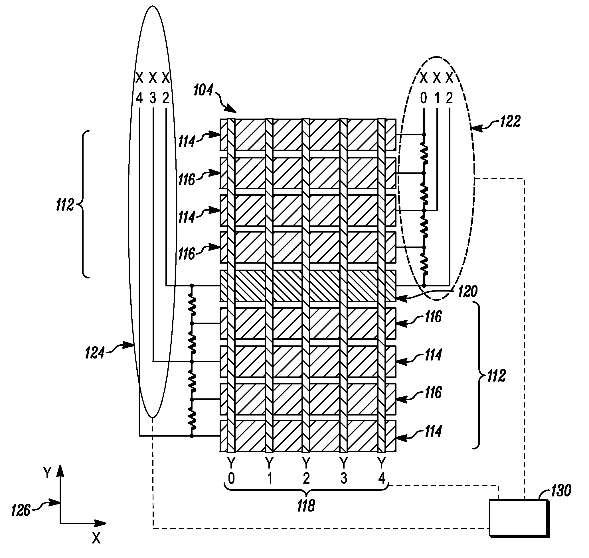
  • Application Information

AI Technical Summary

Benefits of technology

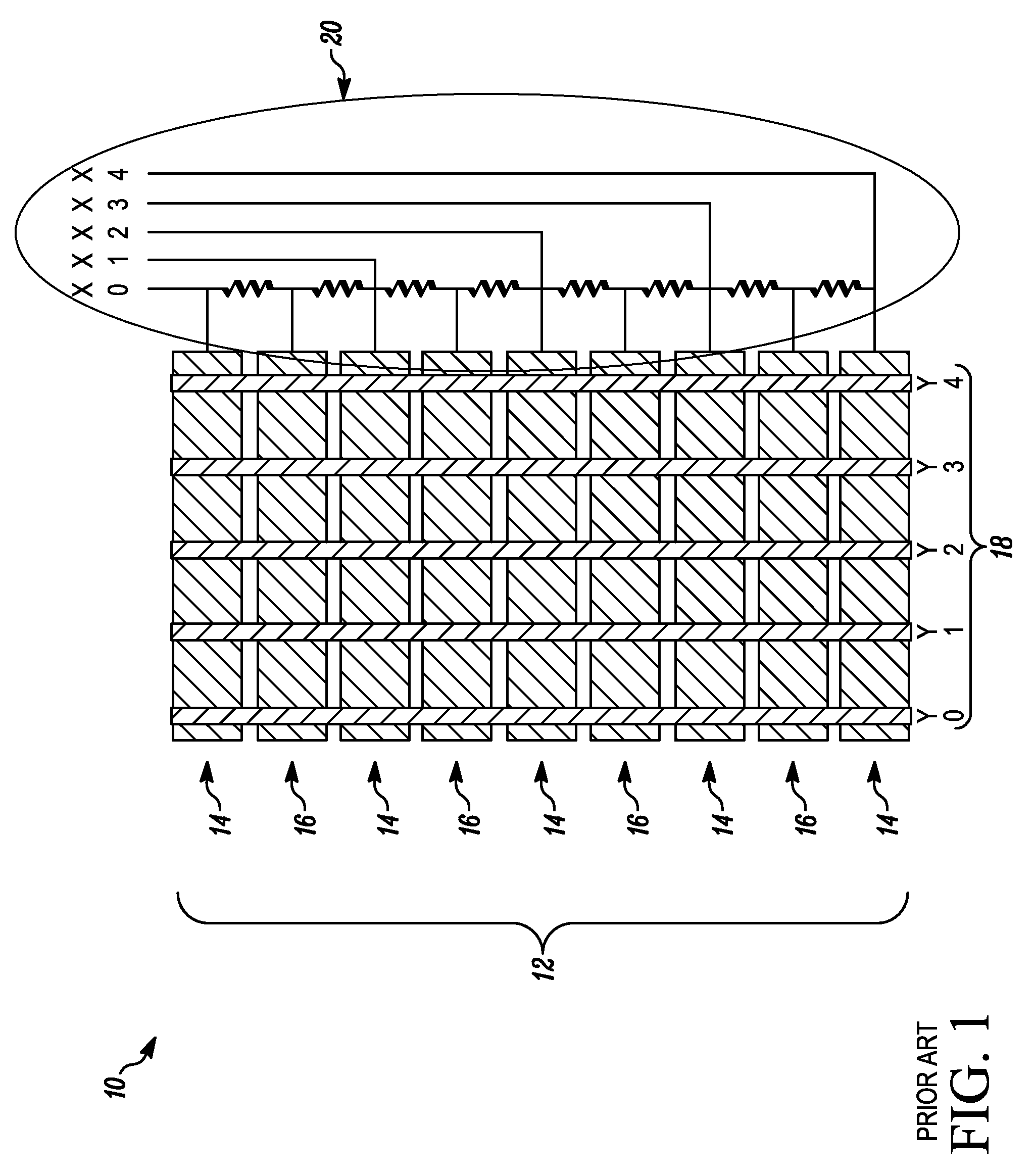
[0004]Having all of the drive lines on one side of the touch screen presents a packaging problem, requiring a large area outside the glass area 18, to print and route the electrodes. Stated differently, they require an asymmetric lens design with a display off-center. In the capacitively interpolated touch screen art, it would be considered an improvement if all the drive electrodes did not have to be connected on the same side, to avoid non-linearities, which could provide greater packaging freedom and design opportunities. It would be considered beneficial, to provide a touch screen device which allows drive lines to be split on either side of the touch screen device, while being highly linear. For example, in such a device the frame area surrounding the touch screen could then be made narrower or thinner.

Problems solved by technology

As mobile communication device technology has continued to improve, the devices have become increasingly smaller and thinner.
The resistive nature of the ITO film requires the resistive ladder to be connected only on one side, as the resistance of crossing from one side to another causes a disadvantageous non-linearity.
Having all of the drive lines on one side of the touch screen presents a packaging problem, requiring a large area outside the glass area 18, to print and route the electrodes.

Method used


Image

  • Method and device for providing an equi-potential touch screen
  • Method and device for providing an equi-potential touch screen
  • Method and device for providing an equi-potential touch screen

Examples


Embodiment Construction

[0009]Disclosed and shown in the figures, is a touch screen device and method of sensing an object near the surface of a touch screen device.

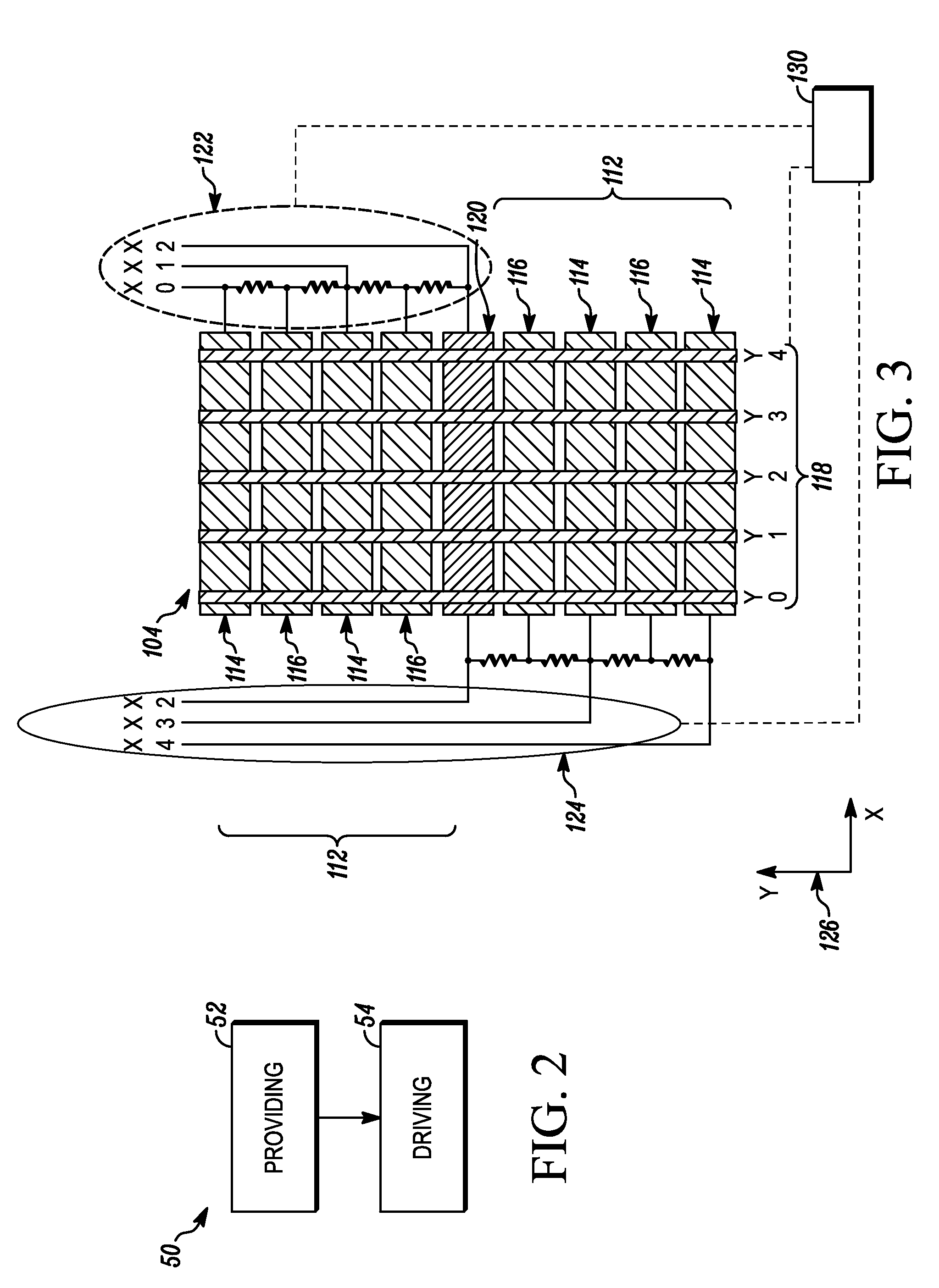
[0010]In one embodiment, a method 50 for providing an equi-potential touch screen, is disclosed and shown in FIG. 2. The method 50 includes: providing 52 a capacitive touch screen including transmit electrodes and receive electrodes combined to form a grid structure configured to provide capacitive signals that allow position of touch to be resolved; and driving 54 a substantially central transmit electrode with equi-potential connection points. Advantageously, the method allows the routing of drive lines on either side of the touch screen, which is highly linear. This provides narrow packaging and reducing electrode complexity. Also, the frame area surrounding the touch screen can be made narrower, as desired, for minimal real estate and optimizing design layout.

[0011]In one embodiment, the method includes providing alternating transmit electr...


PUM


Abstract

Disclosed is a method (50) and device (100) for providing an equi-potential touch screen. The method can include: providing (52) a capacitive touch screen including transmit electrodes and receive electrodes combined to form a grid structure configured to provide capacitive signals that allow position of touch to be resolved; and driving (54) a substantially central transmit electrode with equi-potential connection points. The method (50) and device (100) provide a touch screen device which allows drive lines to be split on either side of the touch screen device, while being highly linear. For example, the frame area surrounding the touch screen can be made narrower or thinner, for minimal real estate and optimizing design layout.

Description

FIELD[0001]Disclosed is a method and device for providing an equi-potential touch screen.BRIEF DESCRIPTION[0002]The makers of mobile communication devices, including those of cellular telephones, are increasingly adding functionality to their devices. While there is a trend toward the inclusion of more features and improvements for current features, there is also a trend toward smaller mobile communication devices. As mobile communication device technology has continued to improve, the devices have become increasingly smaller and thinner. Fewer and / or smaller hardware and software components are therefore desirable when adding new features and making improvements to the current features in the smaller devices. Fewer hardware components may provide a cost benefit to the consumer.[0003]In FIG. 1, a prior art resistively interpolated capacitive touch screen is shown 10. A plurality of drive electrodes 12 include directly connected electrodes 14 and interpolated electrodes 16. The inter...

Claims


Application Information

Patent Timeline
Patent Type & Authority Applications(United States)
IPC IPC(8): G06F3/044
CPCG06F3/044G06F3/0418G06F3/0446G06F3/04166
Inventor CRANFILL, DAVID B.
Owner GOOGLE TECH HLDG LLC
Learn More