
Lubricant free, reduced mass, free-piston, stirling machine having reciprocating piston drivingly linked to rotary electromagnetic transducer moving in rotational oscillation

a technology of electromagnetic transducer and reciprocating piston, which is applied in the direction of machines/engines, mechanical equipment, and gears. it can solve the problems of excessive large machines, poor scaling to higher powers, and central difficulty of the beta configuration

Active Publication Date: 2011-04-28
GLOBAL COOLING
View PDF8 Cites 8 Cited by
  • Summary
  • Abstract
  • Description
  • Claims
  • Application Information

AI Technical Summary

Problems solved by technology

The beta configuration suffers a central difficulty in that it scales poorly to higher powers.
At higher powers, above about 1 kW, the machine becomes excessively large.
The alpha configuration is the preferred embodiment for higher powers but linear alternator / motors do not scale well to the higher powers and therefore lead to large bulky embodiments and / or the need for expensive materials such as cobalt bearing alloys for the magnetic flux paths.
However, linear alternators or motors have a large mass compared to rotating alternators or motors and are therefore difficult to apply to alpha configured Stirling machines particularly at higher power levels of several kilowatts or above.
Crank driven alpha configured machines suffer from the requirement of oil lubrication, extremely tight seals that separate the working gas from the oil and the resulting wear leading to low operational life and poor reliability.
Up to now, there have been no practical mechanisms for alpha machines that have the intrinsic reliability of the beta-type free-piston machine.
However, the alpha machines also have huge problems with friction in their motion converting mechanisms that convert the reciprocating motion of their pistons to rotary motion.
They also consume a lot of power overcoming friction and the friction causes them to wear out too soon.
These prior art machines have suffered severe difficulties in separating the Stirling cycle working gas (usually helium or hydrogen) from the oil lubricant needed to lubricate their motion converting mechanisms.
The seals that separate the working fluid from the oil suffer from high friction leading to power losses and rapid wear-out.

Method used


Image

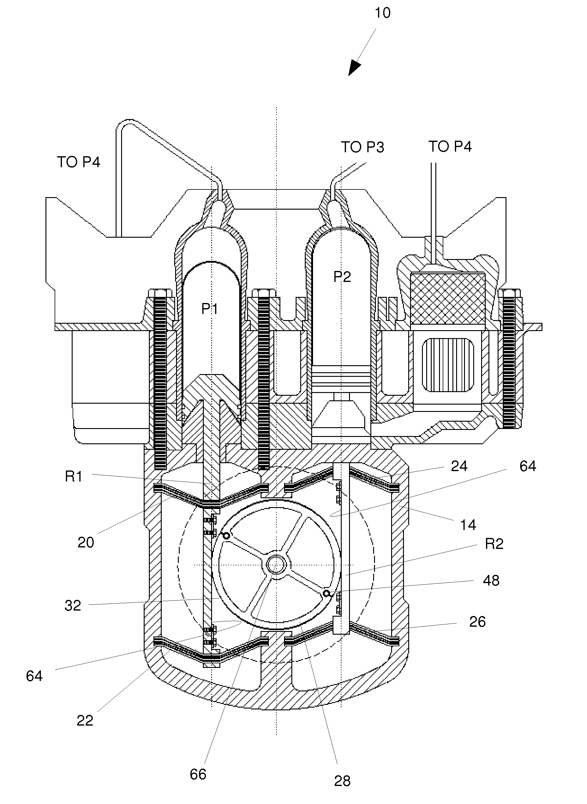
  • Lubricant free, reduced mass, free-piston, stirling machine having reciprocating piston drivingly linked to rotary electromagnetic transducer moving in rotational oscillation
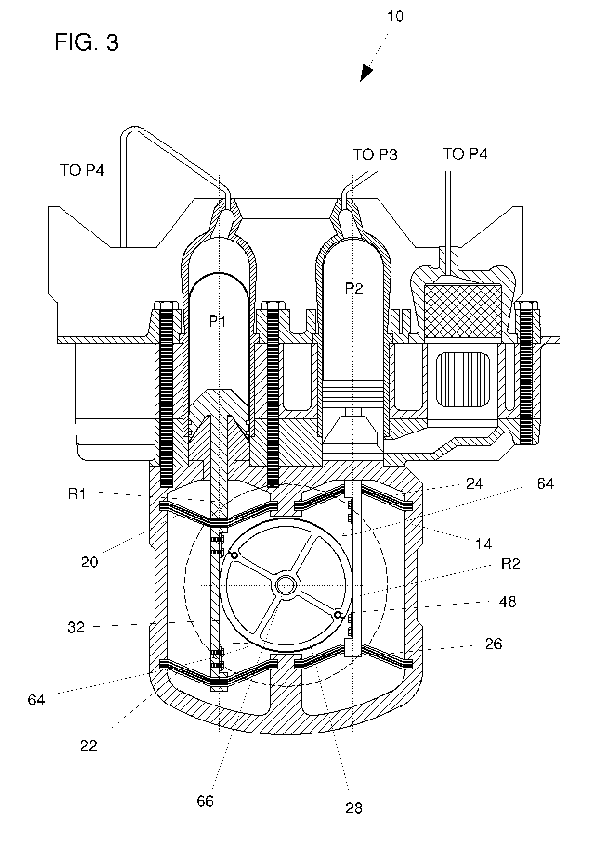
  • Lubricant free, reduced mass, free-piston, stirling machine having reciprocating piston drivingly linked to rotary electromagnetic transducer moving in rotational oscillation
  • Lubricant free, reduced mass, free-piston, stirling machine having reciprocating piston drivingly linked to rotary electromagnetic transducer moving in rotational oscillation

Examples


Embodiment Construction

[0027]Incorporated in this application by reference are: the present inventor's provisional application 61 / 255525 filed Oct. 28, 2009; U.S. Pat. No. 5,753,985; U.S. Pat. No. 7,134,279; and U.S. Pat. No. 7,171,811 on which the present inventor is a co-inventor.

[0028]Definitions

[0029]In describing the present invention, various terms are used. Although the definitions and scope of these terms are known by those skilled in the art, it may be helpful to provide some explanation of them.

[0030]“Stirling machines, Stirling engines, Stirling coolers-heat pumps”. As well known in the art, in a Stirling machine a working gas is confined in a working space that includes an expansion space and a compression space. The working gas is alternately expanded and compressed in order to either do work or to pump heat. The working gas is cyclically shuttled between the compression space and the expansion space which are connected in fluid communication through a heat accepter, a regenerator and a heat ...


PUM


Abstract

A free-piston Stirling machine drivingly coupled to at least one rotary electromagnetic transducer. At least one pulley is oriented in a plane of a reciprocating piston connecting rod. At least one motion translating drive link connects the connecting rod to the pulley by at least two straps so that the pulley moves in rotationally oscillating motion. The two straps extend along an arcuate surface of the pulley into connection to the piston rod at two spaced locations. The pulley is linked to a rotary electromagnetic transducer so that both move in rotationally oscillating motion. Preferably a piston spring resonates the piston at an operating frequency of the Stirling machine and a torsion spring resonates the pulley in rotational oscillation at the operating frequency of the Stirling machine.

Description

CROSS-REFERENCES TO RELATED APPLICATIONS[0001]This application claims the benefit of U.S. Provisional Application No. 61 / 255,525 filed Oct. 28, 2009.[0002]The above prior provisional application is hereby incorporated by reference.STATEMENT REGARDING FEDERALLY-SPONSORED RESEARCH AND DEVELOPMENT[0003](Not Applicable)REFERENCE TO AN APPENDIX[0004](Not Applicable)BACKGROUND OF THE INVENTION[0005]This invention is directed to Stirling machines, both Stirling engines and Stirling coolers or heat pumps, that are drivingly coupled to electromagnetic transducers in the form of rotary electric motors and alternators for generating electrical power or using electrical power to drive a free-piston Stirling machine as a cooler or heat pump. The invention provides a manner of constructing them that reduces their mass and eliminates the friction of the motion converting drive between them and thereby eliminates the need for lubricants that contaminate the working gas of the Stirling machine. The ...

Claims


Application Information

Patent Timeline
IPC IPC(8): H02K7/18
CPCF02G1/044F02G2244/00H02K7/1884F02G2280/20F02G2244/08F16H29/02
Inventor BERCHOWITZ, DAVID M.
Owner GLOBAL COOLING
Learn More