
Pulley for use with toothed belt

a technology for pulling rods and teeth, which is applied in the direction of belts/chains/gearrings, gearing elements, hoisting equipments, etc., can solve the problems of low noise reduction effect of pulling rods, achieve the effect of simplifying the manufacturing process, reducing the manufacturing cost of pulling rods, and reducing engagement nois

Inactive Publication Date: 2011-04-21
TSUBAKIMOTO CHAIN CO
View PDF19 Cites 11 Cited by
  • Summary
  • Abstract
  • Description
  • Claims
  • Application Information

AI Technical Summary

Benefits of technology

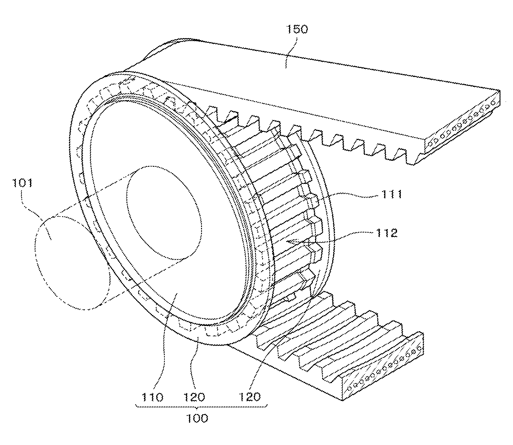
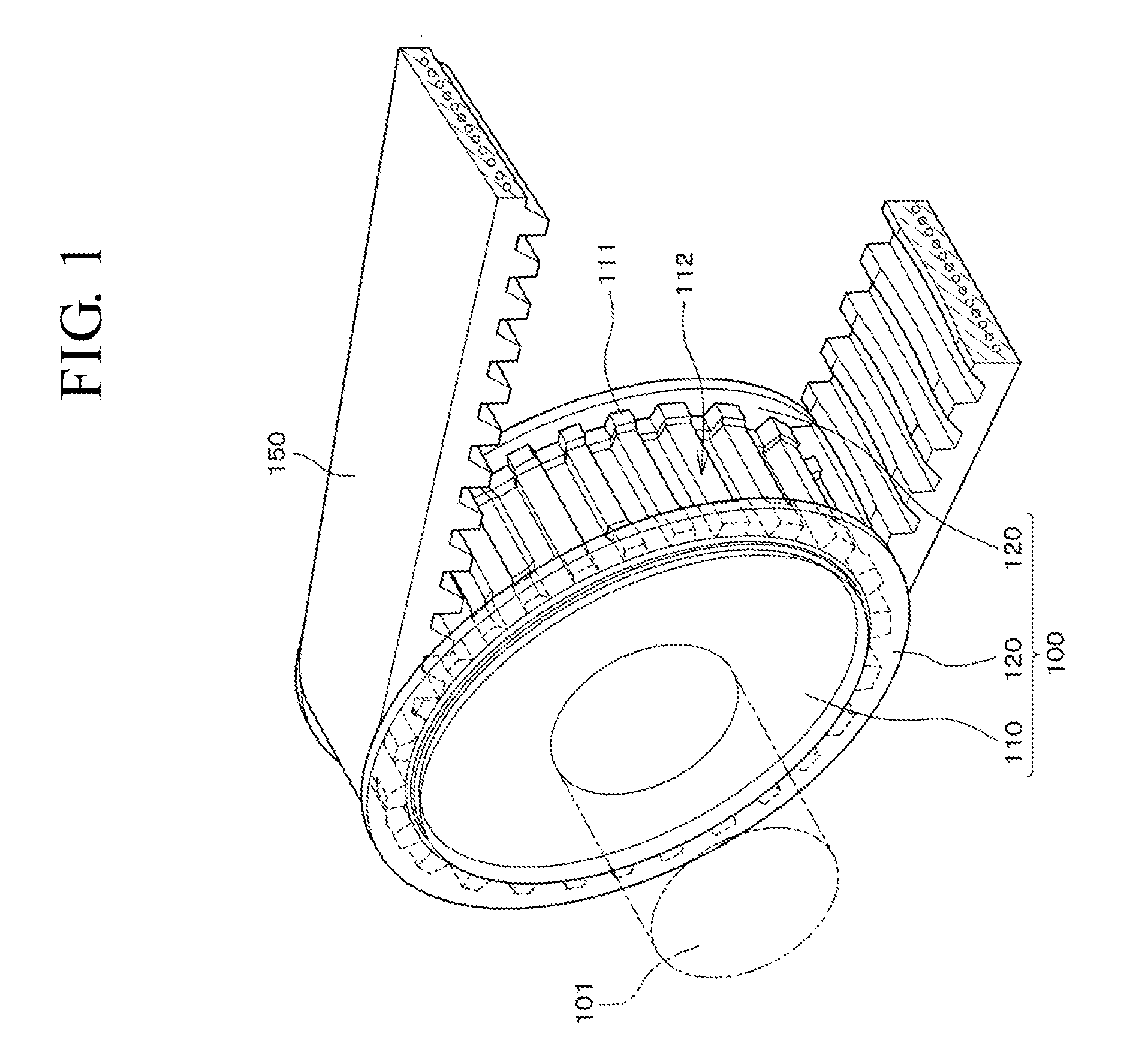
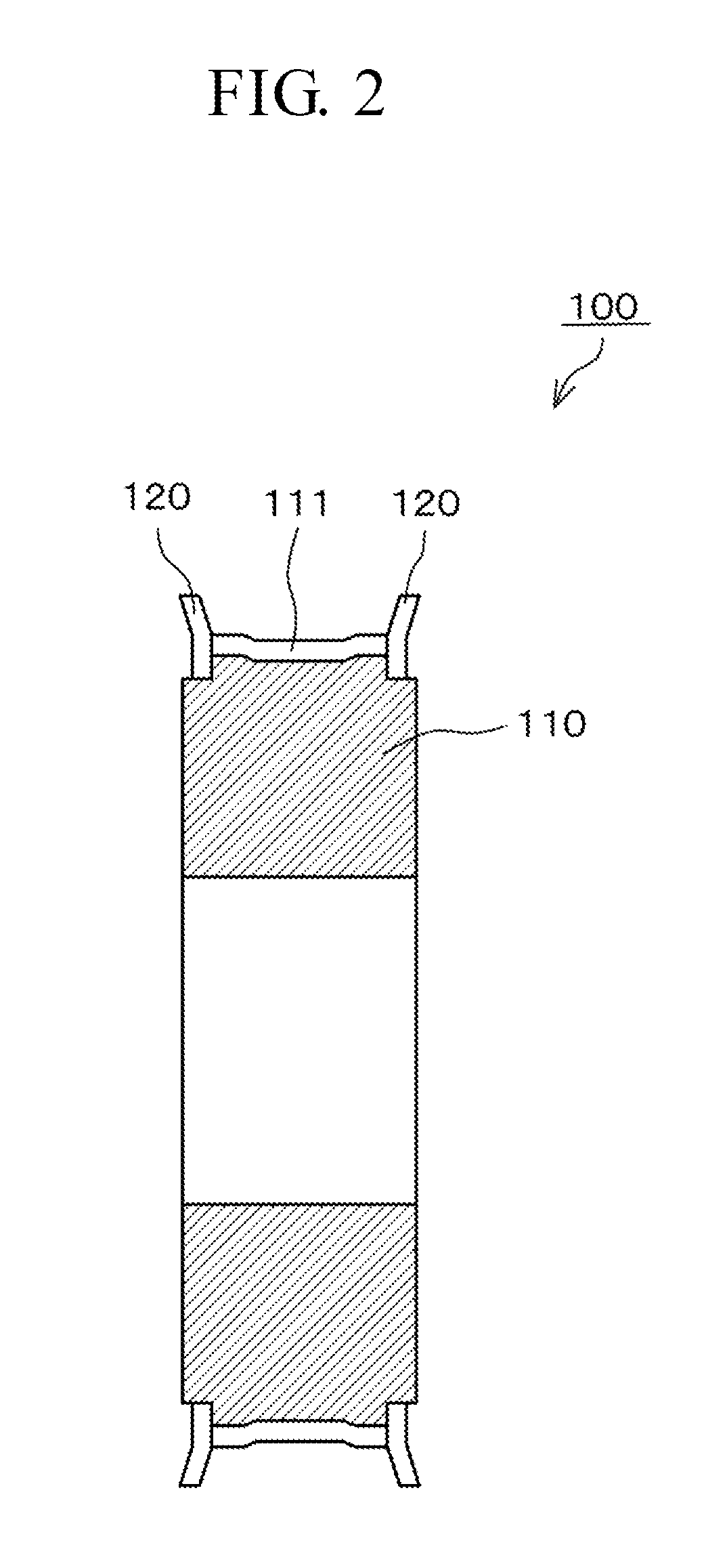
[0013]The toothed-belt pulley of the first aspect of the invention has such advantageous effects that because it is possible to reduce pneumatic and plosive sounds otherwise generated and leaked when the air is compressed when the pulley engages with the toothed belt by discharging the compressed air from the recesses while stably transmitting rotational movements by suppressing the widthwise wobbling of the toothed belt by the flanges.
[0014]Still more, because the toothed belt deformably engages with the teeth of the pulley, the toothed belt will not tightly contact with the teeth, leave the spaces and thus reduce the engagement noise when it engages with the pulley. Furthermore, because the recess may be shallow, the disk may be formed while having the recess from the beginning or the recess may be formed only by a very small amount of cutting works. Accordingly, it is possible to reduce a manufacturing cost of the pulley by simplifying its manufacturing process and to improve a production yield by shortening its manufacturing time.

Problems solved by technology

Still more, the known pulley 600 has another problem that its noise reducing effect is low because an amount of the released air is limited as the width of the cut 612 is narrow and the depth of the cuts 612 is limited by the height of the tooth 611 and because it is unable to prevent the engagement sound generated when the teeth 611 tightly contact with the toothed belt 650.

Method used


Image

  • Pulley for use with toothed belt
  • Pulley for use with toothed belt
  • Pulley for use with toothed belt

Examples


second embodiment

[0040]As shown in FIGS. 7 and 8, a toothed-belt pulley 200 of a second embodiment of the invention has a disk 210 provided with flanges 220 on the both sides of the outer peripheral portion thereof and teeth 211 that engage with a toothed belt around the outer circumference thereof. The teeth 211 have recesses 212 formed while having a certain depth from the surface thereof in the widthwise central part along the whole circumference of the disk 210 including tooth tip portions 214, tooth flank portions 215 and tooth bottom portions 213 of the teeth 211. The teeth 211 also have a concave recess groove 216 that is deeper than the recess 212 in the widthwise central part of the recess 212 along the whole circumference of the disk 210.

[0041]Thereby, a space is created by the recess groove 216 beside the spaces created near the both ends of the recess 212 and the air compressed when the toothed-belt pulley 200 engages with the toothed belt is discharged more out of the spaces of the rece...

third embodiment

[0043]As shown in FIGS. 9 and 10, a toothed-belt pulley 300 of a third embodiment of the invention has a disk 310 provided with flanges 320 on the both sides of the outer peripheral portion thereof and teeth 311 that engage with a toothed belt around the outer circumference thereof. The teeth 311 have recesses 313 formed while having a certain depth from the surface thereof in the widthwise central part along the whole circumference of the disk 310 including tooth tip portions 314, tooth flank portions 315 and tooth bottom portions 313 of the teeth 311 and also have projecting portion 317 in the widthwise central part of the recess 312 along the whole circumference of the disk 310.

[0044]Thereby, spaces are created on the both sides of the projecting portion 317 because the toothed belt contacts with the projecting portion 317 formed in the widthwise central part of the recess 312 even if the toothed belt deflects in arch and the spaces created near the both ends of the recess 312 ar...

fourth embodiment

[0046]As shown in FIG. 11, a toothed-belt pulley 400 of a fourth embodiment of the invention has a disk 410 provided with flanges 420 on the both sides of the outer peripheral portion thereof and with teeth 411 that are to be engaged with a toothed belt on the outer circumference. The teeth 411 have recesses formed in the widthwise central part of the teeth in the same manner with the first through third embodiments and the flanges 420 have through holes 421 penetrating therethrough at positions corresponding to the tooth tips of the respective teeth 411.

[0047]Thereby, the air compressed when the teeth of the pulley engage with the toothed belt and discharged in the direction of the flanges is discharged through the through holes 421 while being suppressed to increase its pressure and flow rate, it is possible to reduce the pneumatic and plosive sounds otherwise generated when the compressed air leaks out of the slight gap between the toothed belt and the flange 420.

[0048]It is note...


PUM


Abstract

The invention provides a toothed-belt pulley that is capable of reducing pneumatic and plosive sounds and of reducing engagement noises while stably transmitting rotational movements by suppressing widthwise wobbling of a toothed belt and while reducing a manufacturing cost of the pulley by simplifying its manufacturing process and of improving a production yield by shortening its manufacturing time. The toothed-belt pulley has a disk whose inner circumference is fittingly attached to a rotary shaft and which is provided with teeth to be engaged with the toothed belt around the outer circumference and flanges erected on the both outer sides of the toothed belt, wherein each of the teeth has a concaved recess with which the toothed belt deformably engages in the widthwise center part thereof.

Description

CROSS REFERENCE TO RELATED APPLICATIONS[0001]This application claims the foreign priority benefit under Title 35, United States Code, §119 (a)-(d) of Japanese Patent Application No. 2009-238073, filed on Oct. 15, 2009 in the Japan Patent Office, the disclosure of which is herein incorporated by reference in its entirety.BACKGROUND OF THE INVENTION[0002]1. Field of the Invention[0003]The present invention relates to a pulley for use with a toothed belt, which is referred to hereinafter as a ‘toothed-belt pulley,’ the toothed-belt pulley for engaging with the toothed belt to transmit rotational movements.[0004]2. Related Art[0005]Various toothed-belt pulley systems are currently known in the art. The toothed-belt pulleys have teeth which are engaged with a toothed belt around the outer circumference thereof and flanges erected on the both outer sides of the toothed belt. One example of one such system is disclosed in page 4 and FIG. 3 of Japanese Patent Application Laid-open No. 2001-...

Claims


Application Information

Patent Timeline
IPC IPC(8): F16H55/10
CPCF16H57/0006F16H55/171
Inventor KANAMORI, MASARUTOMOBUCHI, MASATO
Owner TSUBAKIMOTO CHAIN CO
Learn More