
Chain transmission device

a transmission device and chain technology, applied in the direction of belts/chains/gearings, chain elements, chain elements, etc., can solve the problems of reducing elongation of the chain, and difficulty in obtaining high strength, so as to reduce the strength of the chain, the effect of significantly reducing the noise of engagement and significant reducing the noise of vibration and nois

Active Publication Date: 2009-10-01
TSUBAKIMOTO CHAIN CO
View PDF15 Cites 4 Cited by
  • Summary
  • Abstract
  • Description
  • Claims
  • Application Information

AI Technical Summary

Benefits of technology

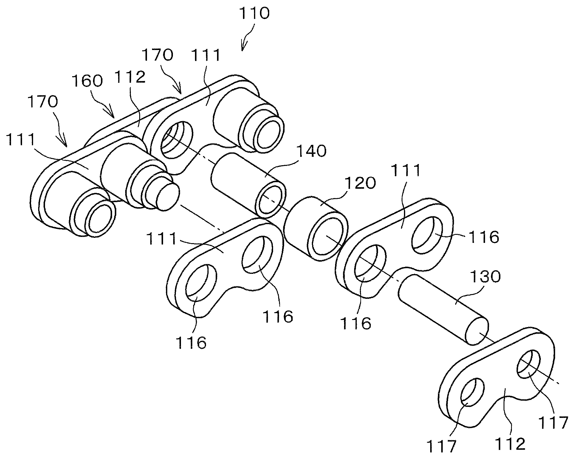
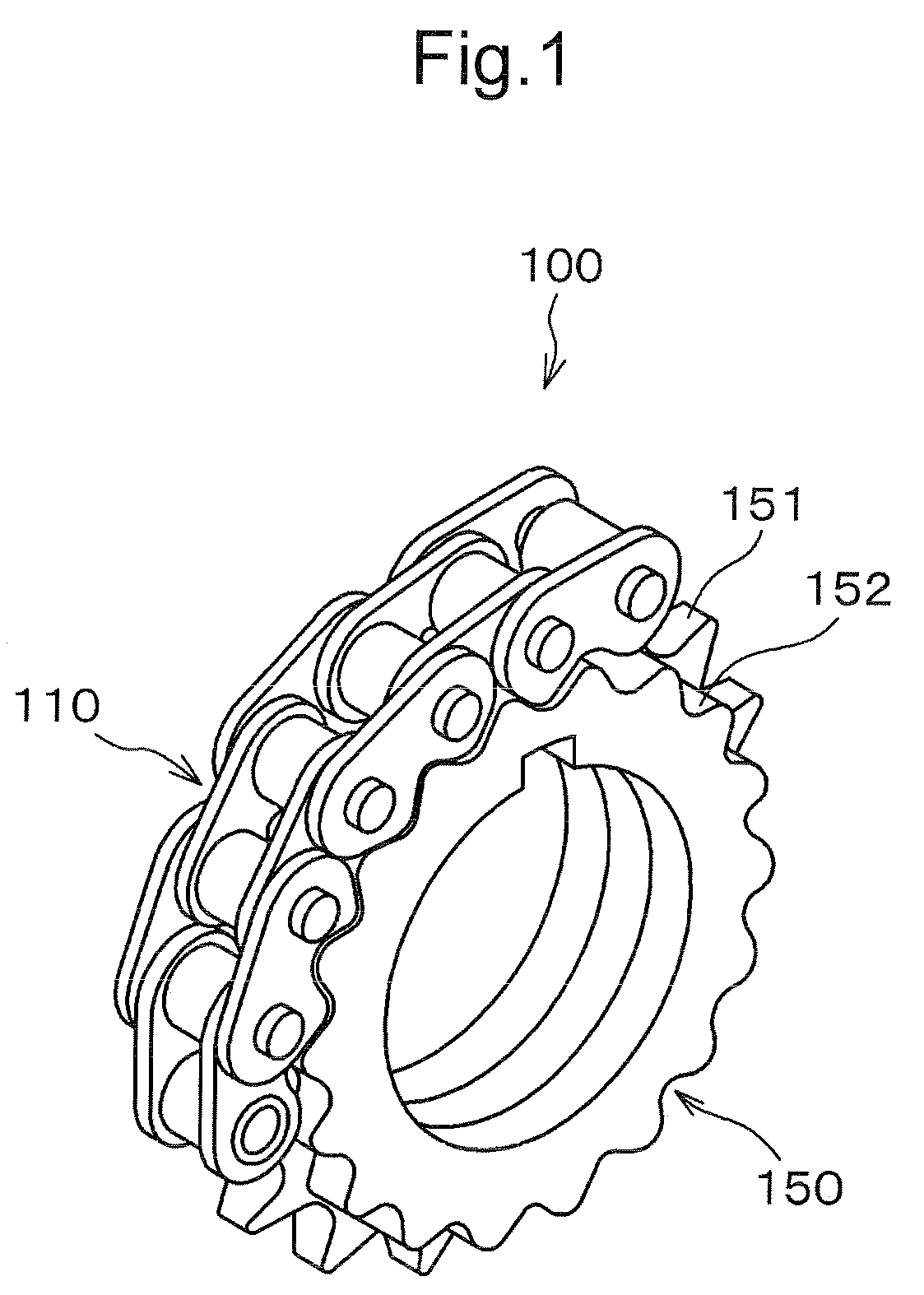
[0015]Engagement noises are significantly reduced, in particular because the bushings or rollers are prevented from colliding with the sprocket teeth as in the case of a transmission using a conventional roller chain or rollerless bushing chain.
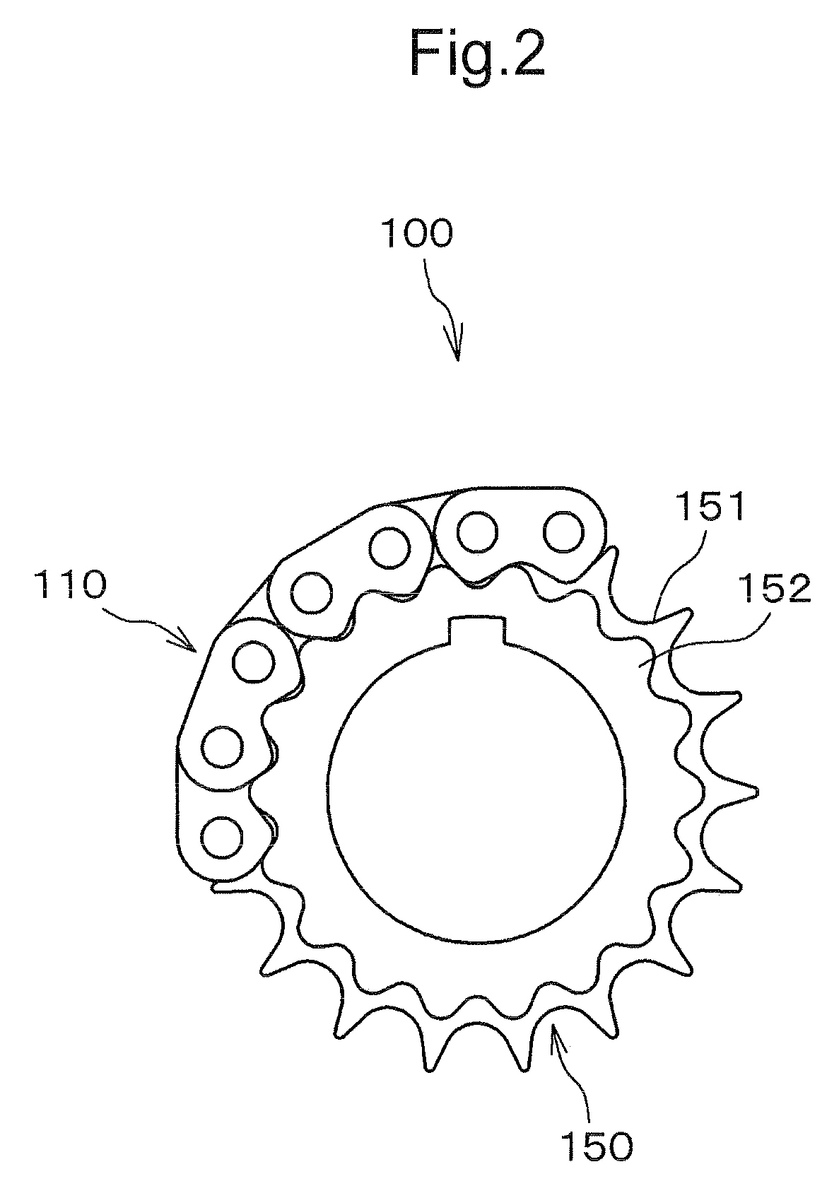
[0016]Transmission of power is primarily through bushing or roller. Therefore a decrease in strength of the chain, due to elongation as a result of wear of the connecting pins, can be prevented. At the same time, since the outer flanks of the link plate teeth come into contact with the side sprocket teeth, the link plates are positioned so that bushings or rollers are stably seated on the tooth gap bottoms of the central sprocket teeth, and vibration and noise can be significantly reduced.
[0017]When side sprocket teeth are provided on both sides of the central sprocket teeth, power is uniformly transmitted by both sides of the chain, and vibration and noise are further reduced.
[0018]When link plate teeth are provided on both the upper and lower sides of the outer and inner link plates, assembly of the chain becomes easier as it is unnecessary to take into account the direction of the link plate teeth. At the same time, the chain can be used in a transmission in which the chain meshes with sprockets on the exterior of the loop formed by the chain as well as with sprockets on the interior of the loop.

Problems solved by technology

A chain transmission using a convention silent chain exhibits significant elongation due to wear of its connecting pins, and the elongation of the chain is accompanied by a reduction in its strength.
In a chain transmission using a conventional roller chain, obtaining high strength is difficult, especially because of difficulties in strengthening the rollers.
Furthermore, conventional roller chains produce a large amount of noise as they come into engagement with a sprocket.
In the hybrid chain describe above, in which the outer link plates function as a silent chain, the problem of elongation due to wear of the connecting pins has not been overcome.
Thus, as in the case of a conventional silent chain, elongation of the chain occurs, and is accompanied by a decrease in strength.
Another problem with the hybrid chain is that, because it has a total of eight plates in the direction of the chain width, and various different components, assembly of the chain is complicated.

Method used


Image

  • Chain transmission device
  • Chain transmission device
  • Chain transmission device

Examples


Embodiment Construction

[0030]In the chain transmission according to the invention, the chain construction is similar to that of a roller chain or rollerless bushing chain. However, the link plates are formed with front and rear teeth similar to those of a conventional silent chain. The rollers or bushings mesh with central teeth on a sprocket, and the teeth formed on link plates mesh with side sprocket teeth, preferably on both sides of the central teeth. The rollers and teeth are formed so that engagement of the elements of the chain with the sprocket teeth takes place in a sequence such that engagement noise is reduced while elongation and reduction in strength due to wear of the connecting pins are also reduced. In addition, the number of chain components is small and assembly of the chain is relatively simple.

[0031]As shown in FIGS. 1 and 2, in the chain transmission according to the invention, a chain 110 is wrapped around a sprocket 150 to transmit driving force from the chain to the sprocket, or fr...


PUM


Abstract

In a chain transmission, the link plates of a roller chain or rollerless bushing chain are formed with pairs of teeth. A sprocket has a central set of sprocket teeth for meshing with the rollers or bushings, and sets of side sprocket teeth for meshing with the sprocket. The teeth of the link plates function as a silent chain. After an inner flank of a link plate tooth comes into contact with a side sprocket tooth, a roller and an outer flank of the link plate tooth are seated on the sprocket.

Description

CROSS-REFERENCE TO RELATED APPLICATION[0001]This application claims priority on the basis of Japanese patent application 2008-090501, filed Mar. 31, 2008. The disclosure of Japanese application 2008-090501 is hereby incorporated by reference.FIELD OF THE INVENTION[0002]The invention relates to a chain transmission in a chain is wound around sprockets to transmit power. A typical application of a chain transmission is the transmission of power to auxiliary equipment such as an oil pump in an engine, or the transmission of power from an engine crankshaft to the camshafts that operate the engine's intake and exhaust valves.BACKGROUND OF THE INVENTION[0003]In chain transmissions, it is common to use a roller chain, a rollerless bushing chain, or a silent chain. Furthermore, hybrid chains in which the features of a silent chain and the features of a roller chain or bushing chain are combined have been used in a chain transmission.[0004]A typical chain transmission incorporating such a hy...

Claims


Application Information

Patent Timeline
Patent Type & Authority Applications(United States)
IPC IPC(8): F16G13/04
CPCF16H7/06F16G13/04
Inventor SAKURA, SHUNJIHIRAI, AKIRA
Owner TSUBAKIMOTO CHAIN CO
Learn More