
Scanning exposure apparatus, control apparatus and method of manufacturing device

Inactive Publication Date: 2011-04-21
CANON KK
View PDF1 Cites 10 Cited by
  • Summary
  • Abstract
  • Description
  • Claims
  • Application Information

AI Technical Summary

Benefits of technology

[0007]The present invention provides a technique advantageous in throughpu

Problems solved by technology

Unfortunately, in the master-slave synchronization control, the symmetry of response characteristics between axes deteriorates.

Method used


Image

  • Scanning exposure apparatus, control apparatus and method of manufacturing device
  • Scanning exposure apparatus, control apparatus and method of manufacturing device
  • Scanning exposure apparatus, control apparatus and method of manufacturing device

Examples


first embodiment

[0018]A position control apparatus 100 according to the first embodiment of the present invention will be described with reference to FIG. 1. The position control apparatus 100 can be designed as an apparatus which synchronously controls an original stage 55 and substrate stage 56 of an exposure apparatus EX as illustrated in, for example, FIG. 5. An example in which the position control apparatus 100 is designed as an apparatus that synchronously controls the original stage 55 and substrate stage 56 of the exposure apparatus EX will be explained below.

[0019]A first controlled object 8a includes the original stage (first stage) 55, an original stage driving mechanism (first stage driving mechanism) which drives it, and a laser interferometer (first measuring unit) 52, and has a first transfer characteristic or transfer function P1. A second controlled object 8b includes the substrate stage (second stage) 56, a substrate stage driving mechanism (second stage driving mechanism) which ...

second embodiment

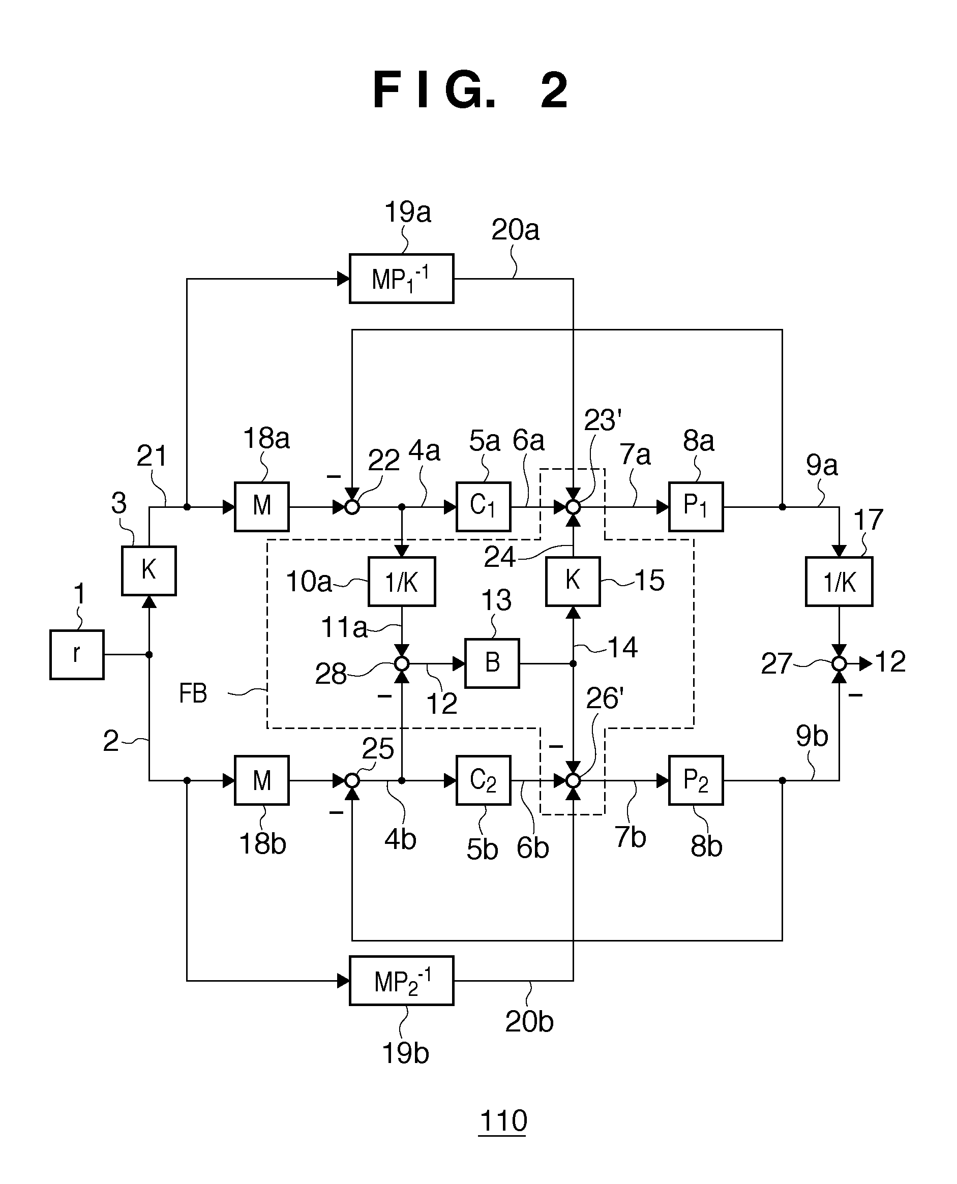
[0025]A position control apparatus 110 according to the second embodiment of the present invention will be described with reference to FIG. 2. The second embodiment will give an improvement to the first embodiment. Note that the same reference numerals as in the constituent elements of the position control apparatus 100 according to the first embodiment denote the same constituent elements of the position control apparatus 110 in the second embodiment. The second embodiment is suitable when a first transfer characteristic (transfer function) P1 of a first controlled object 8a including an original stage 55, and a second transfer characteristic (transfer function) P2 of a second controlled object 8b including a substrate stage 56 are too complex to sufficiently equalize the transfer characteristics C1P1 and C2P2 described earlier. In the position control apparatus 110, parts other than the first controlled object 8a and second controlled object 8b can be called a controller CNT.

[0026...


PUM


Abstract

A scanning exposure apparatus includes a first feedback loop including a first controlled object including an original stage and controlling a position of the original stage, a second feedback loop including a second controlled object including a substrate stage and controlling a position of the substrate stage, and a feedback unit including a first calculator and feed backing a synchronization error between the original stage and the substrate stage to the first feedback loop and the second feedback loop via the first calculator, wherein a transfer function from a first target value for the first controlled object to a first controlled value of the first controlled object and that from a second target value for the second controlled object to a second controlled value of the second controlled object are equal, and the exposure is performed at least during a period in which the original and the substrate are accelerated.

Description

BACKGROUND OF THE INVENTION[0001]1. Field of the Invention[0002]The present invention relates to a scanning exposure apparatus, a control apparatus, and a method of manufacturing a device.[0003]2. Description of the Related Art[0004]An exposure apparatus projects the pattern of an original (reticle) onto a substrate (for example, a wafer or a glass plate) by a projection optical system to expose the substrate. The substrate is coated with a photosensitive material (photoresist). The pattern of the original is transferred onto the photosensitive material as a latent image pattern by exposing the photosensitive material. The latent image pattern is developed into a physical pattern (resist pattern) through a development process. To transfer the pattern of the original onto the substrate, alignment between the original and the substrate is of prime importance. The original is supported by an original stage having an original chuck, while the substrate is supported by a substrate stage ...

Claims


Application Information

Patent Timeline
IPC IPC(8): G03B27/42
CPCG03F7/70725
Inventor FUKAGAWA, YOUZOUHIRATA, MITSUO
Owner CANON KK
Learn More