Injection method and device for controlling an injection process in an internal combustion engine

a technology of injection process and injection method, which is applied in the direction of electric control, liquid fuel feeder, machines/engines, etc., can solve the problems of over-enriching of air/fuel mixture, large metering range of fuel injectors, and high technical requirements, and achieve the effect of reducing static flow

Inactive Publication Date: 2011-04-07
ROBERT BOSCH GMBH
View PDF17 Cites 5 Cited by
  • Summary
  • Abstract
  • Description
  • Claims
  • Application Information

AI Technical Summary

Benefits of technology

[0008]It is an object of the present invention to provide a method for the activation of a fuel injector during so-called enrichment operation in high-load operation, in which a cooling fuel quantity is injected to cool the combustion exhaust gases, the fuel injector being able to be designed with a reduced static flow in relation to conventional fuel injectors.
[0011]Since the cooling fuel quantity is not required for torque generation, it is noncritical to inject it at least partially after combustion. The cooling fuel quantity, which is required for cooling down the temperature of the combustion exhaust gas, still cools the combustion exhaust gases in the combustion chamber, so that already cooled combustion exhaust gases are expelled in the exhaust stroke. Since the drive fuel quantity to be injected during the intake stroke, which is required for torque generation, is reduced in comparison to typical operation by the cooling fuel component, the fuel quantity thus reduced during the first injection time window may be injected using a lower flow of the fuel injector. The fuel injector may thus be designed in such a way that the static flow at the operating point under full load at rated speed is reduced in relation to typically used fuel injectors. This results in more precise metering of the fuel quantity in the case of operating points having small injection quantities, which may result in improvement of the smooth running and the emissions in the case of operating points of small injection quantities.
[0018]According to one specific embodiment, the part of the cooling fuel quantity which is injected jointly with the drive fuel quantity before the combustion in the cylinder may be metered as a function of an ignition angle, so that knocking of the internal combustion engine is suppressed.

Problems solved by technology

However, fuel injectors having a large metering range are complex to implement.
In particular, it is technically demanding in the case of fuel injectors which have a high static flow to ensure precise fuel metering in the case of low fuel quantities.
In the case of turbocharged internal combustion engines having a high degree of charging (high charging pressure), in which a high spread is required between the static flow rate and the minimum settable flow rate, this often results in problems in the case of metering of small fuel quantities.
In particular, injecting an excessively high fuel quantity for torque generation may result in over-enrichment of the air / fuel mixture.

Method used


Image

  • Injection method and device for controlling an injection process in an internal combustion engine
  • Injection method and device for controlling an injection process in an internal combustion engine
  • Injection method and device for controlling an injection process in an internal combustion engine

Examples


Embodiment Construction

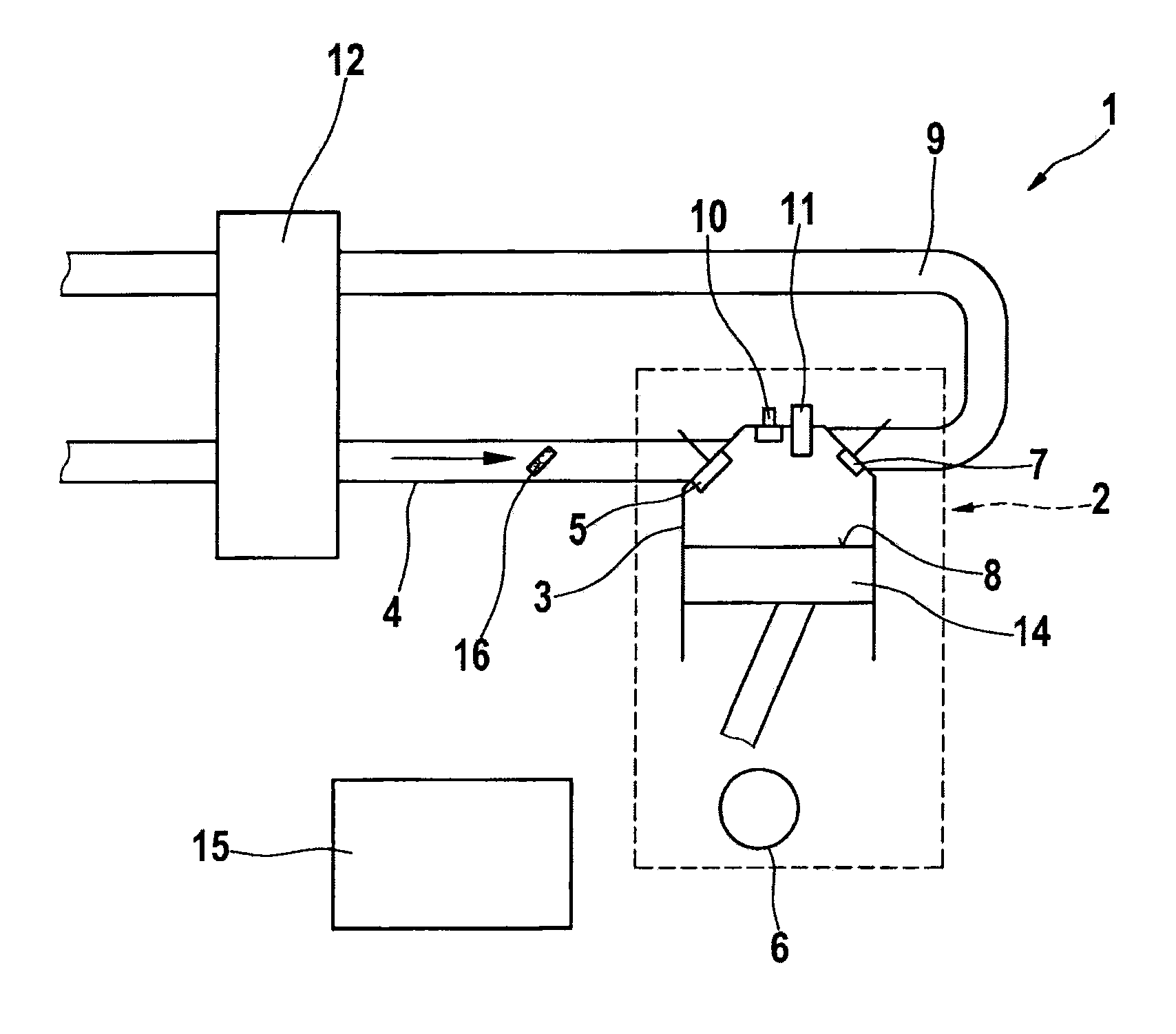
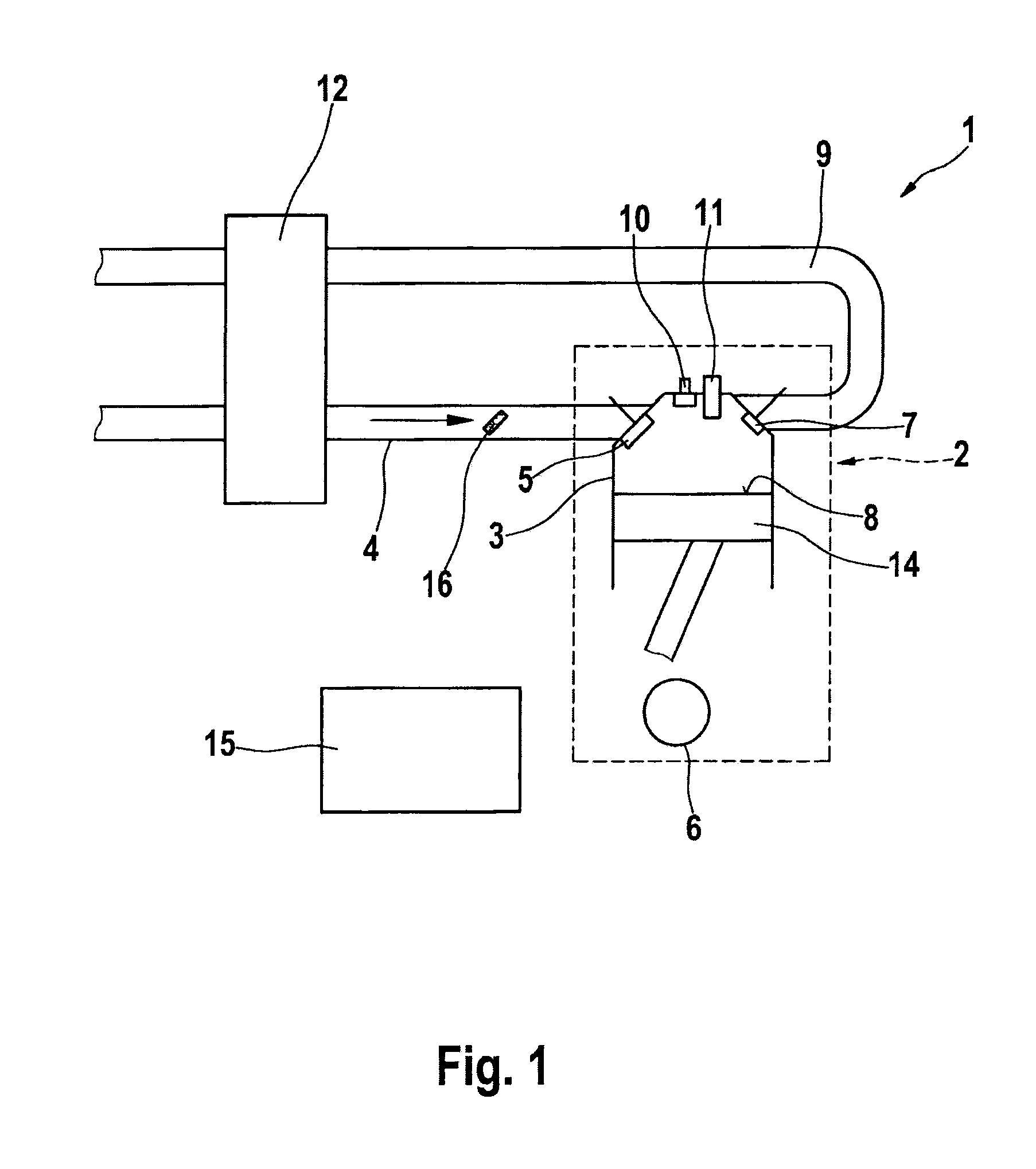
[0032]An engine system 1 having an internal combustion engine 2, in particular a gasoline engine, is shown in FIG. 1. Internal combustion engine 2 is shown having only one cylinder 3 for the sake of simplicity; however, the internal combustion engine may have multiple cylinders, which are coupled to one another so that they have offset strokes to one another.

[0033]Cylinder 3 is connected to an air supply system 4 and has an intake valve 5. Intake valve 5 may be coupled to a crankshaft 6, in order to let air into a combustion chamber 8 of cylinder 3 during an intake time window controlled by a crankshaft angle of crankshaft 6. Alternatively, conventional electrically controlled intake valves are available.

[0034]Furthermore, the cylinder has an outlet valve 7, in order to let combustion gases out of combustion chamber 8 of cylinder 3 into an exhaust system 9. Outlet valve 7 may also be activated either via a position of crankshaft 6 as a function of a crankshaft angle or, alternativel...


PUM


Abstract

A method for controlling an injection of fuel in an internal combustion engine, in particular in a gasoline engine having direct injection, a drive fuel quantity, which indicates the fuel quantity required by the internal combustion engine to provide a torque, being injected in a working cycle before a combustion stroke of the working cycle into a cylinder of the internal combustion engine, a cooling fuel quantity, which indicates the fuel quantity which is used to cool the combustion exhaust gases, being injected in the working cycle in addition to the drive fuel quantity, at least part of the cooling fuel quantity being injected after completion of the combustion in the combustion stroke and / or the immediately following exhaust stroke of the working cycle.

Description

CROSS REFERENCE[0001]The present application claims the benefit under 35 U.S.C. §119 of German Patent Application No. 102010029728.3 filed on Jun. 7, 2010 and German Patent Application No. 102009029332.9 filed on Sep. 10, 2009, each of which is expressly incorporated herein by reference in its entirety.FIELD OF THE INVENTION[0002]The present invention relates to injection methods, in particular for internal combustion engines having direct fuel injection, and devices for controlling the injection of fuel into a combustion chamber of an internal combustion engine.BACKGROUND INFORMATION[0003]In the case of internal combustion engines having direct fuel injection, in addition to a drive fuel quantity which is required for combustion, fuel is injected to cool the exhaust gas in the combustion chamber of the particular cylinder in a full-load range. The injection of this so-called cooling fuel quantity in high-load operation is referred to as enrichment and is used for the purpose of pro...

Claims


Application Information

Patent Timeline
Patent Type & Authority Applications(United States)
IPC IPC(8): F02M69/04
CPCF02D35/027Y02T10/44F02D2041/0265F02D41/405Y02T10/40
Inventor MOESSNER, DAVIDSTORCH, AXELBOERKEL, WOLFGANGFRIEDMANN, HARRYCREPIN, PIERRE-YVES
Owner ROBERT BOSCH GMBH
Why Eureka
Try Eureka