
Phase change random access memory apparatus and write control method for the same

a random access memory and phase change technology, applied in the field of semiconductor devices, can solve the problems of large amount of programming time required for set data, limited electric current driving capability, and deterioration of cell data state, so as to reduce the time required for programming operation.

Active Publication Date: 2011-03-31
SK HYNIX INC
View PDF4 Cites 3 Cited by
  • Summary
  • Abstract
  • Description
  • Claims
  • Application Information

AI Technical Summary

Benefits of technology

[0025]Accordingly, there is a need for an improved phase change random access memory apparatus and a related write control method that may overcome one or more of the problems discussed above. One aspect of the present invention provides a phase change random access memory apparatus that can minimize the time required for a programming operation, and a write control method for the phase change random access memory apparatus.
[0026]Another aspect of the present invention provides a phase change random access memory apparatus that can be easily applied to digital apparatuses using other nonvolatile memory apparatuses, and a write control method for the phase change random access memory apparatus.

Problems solved by technology

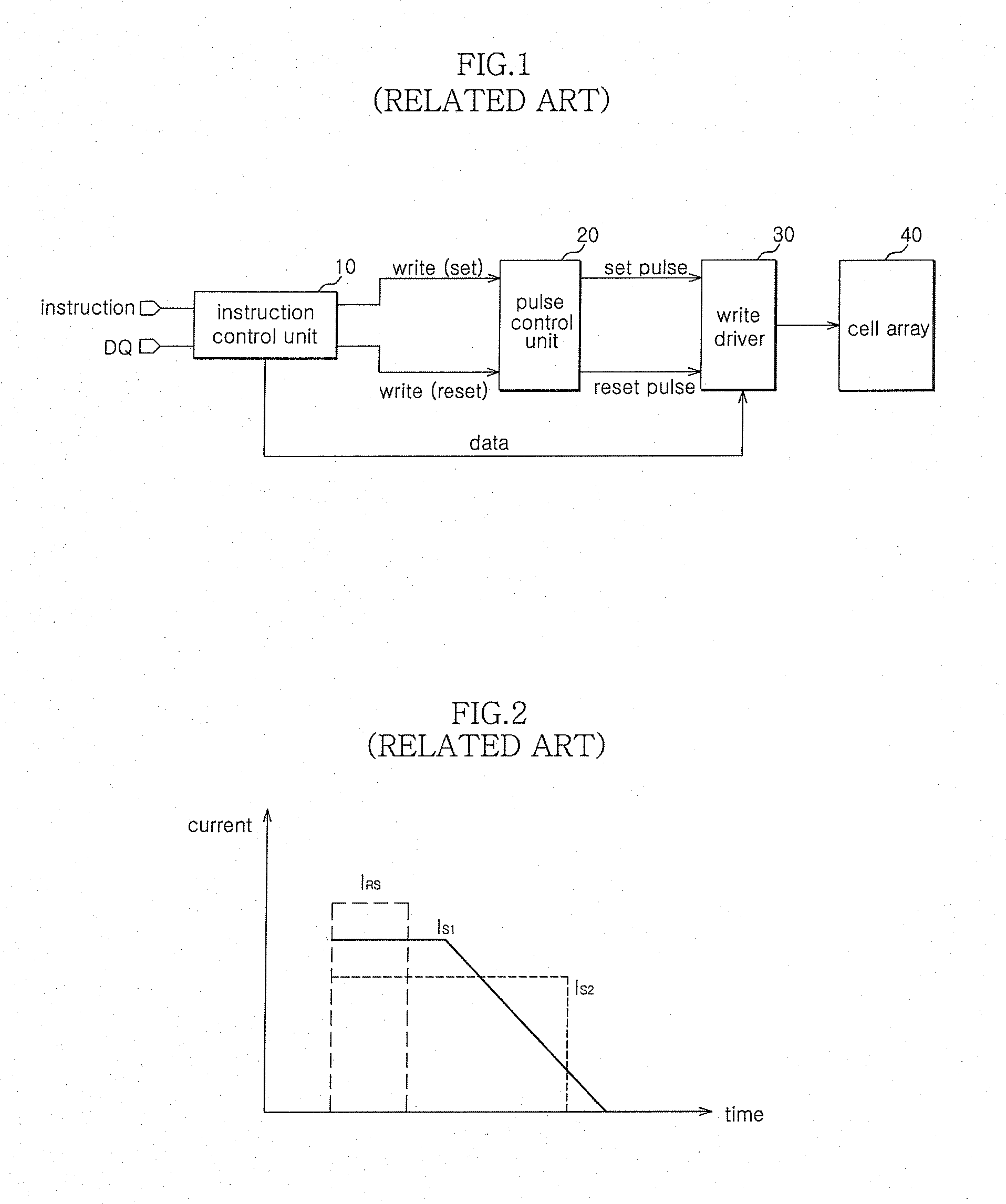
As described above, a large amount of electric current is required to program the cells of a phase change random access memory, and particularly, a large amount of programming time is required for the set data with a large amount of electric current.
Moreover, since more amount of electric current is needed to simultaneously program a plurality of cells, the electric current driving capability is limited considering the characteristics of PCRAMs that simultaneously write set / reset data.
In addition, since the set / reset data is simultaneously written, the state of the cell data may be deteriorated.
This in turn results in allotting unnecessarily long time to the reset operation which ultimately adversely affects the optimization of the operation speed.
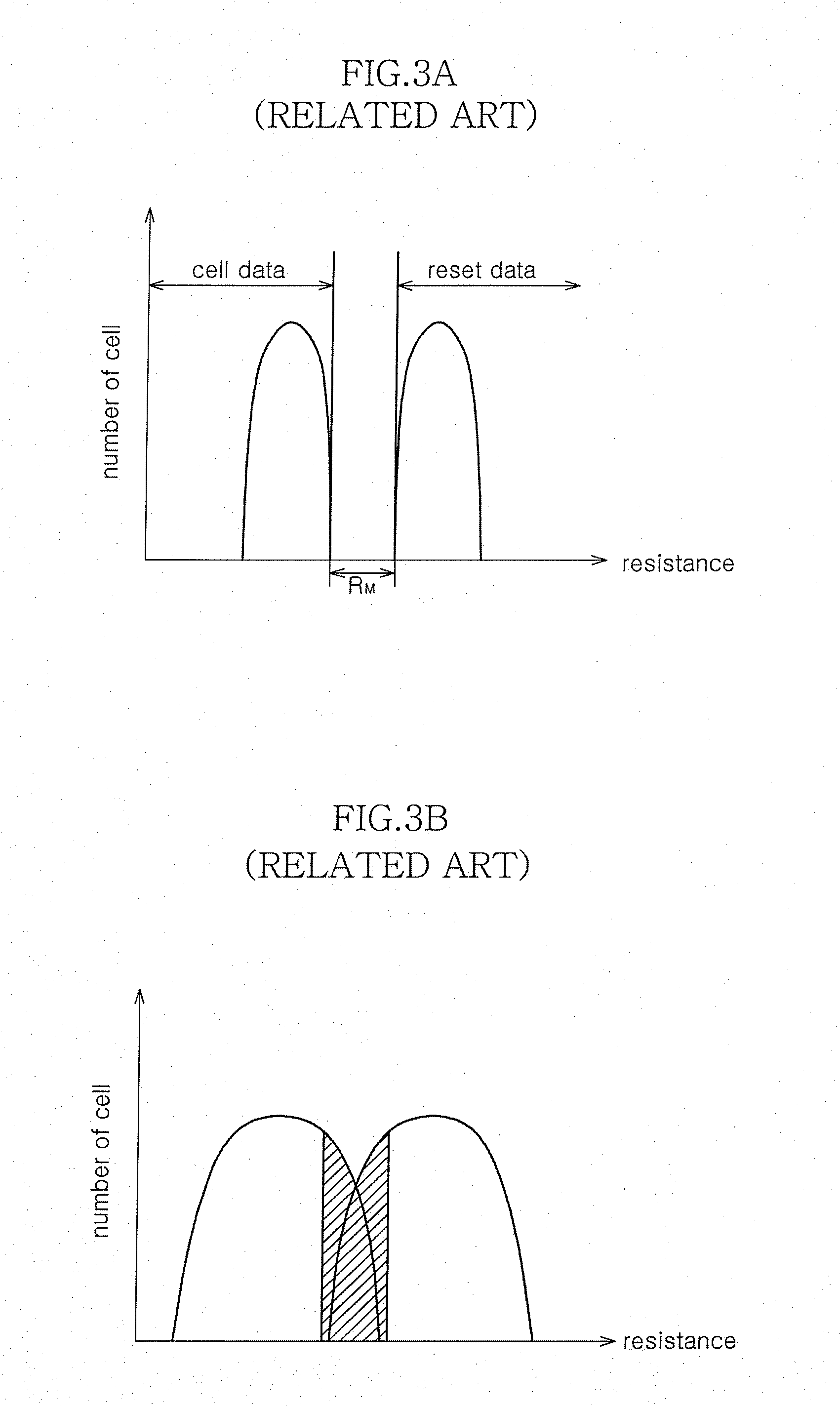
If that happens, it is relatively hard to ensure the resistance difference between the phase change material storing the set data and the phase change material storing the reset data, such that unintended data may be stored in each memory cell.
Further, it takes longer time to write set data than reset data.
Accordingly, the number of programmable cells for a limited program period is necessarily limited and the erase period is inefficiently wasted.

Method used


Image

  • Phase change random access memory apparatus and write control method for the same
  • Phase change random access memory apparatus and write control method for the same
  • Phase change random access memory apparatus and write control method for the same

Examples


Embodiment Construction

[0046]Reference will now be made in detail to the exemplary embodiments consistent with the present disclosure examples of which are illustrated in the accompanying drawings. Wherever possible, the same reference characters will be used throughout the drawings to refer to the same or like parts.

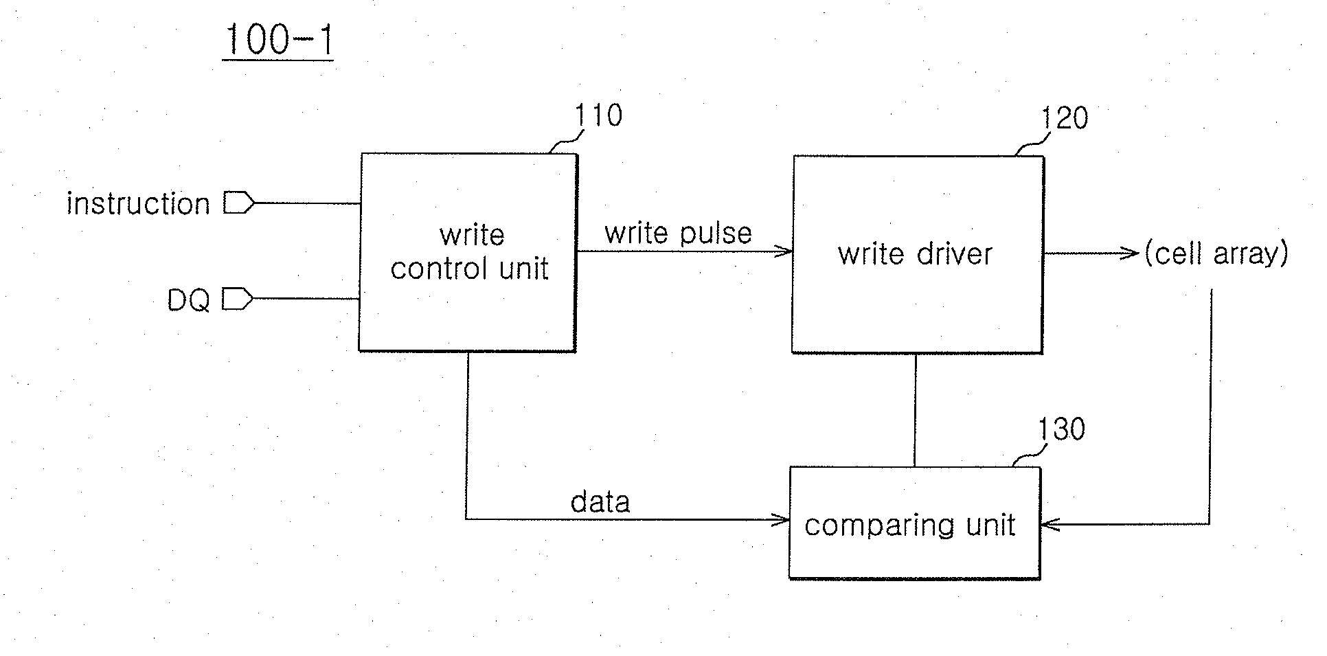
[0047]FIG. 5 is a diagram illustrating the configuration of a phase change random access memory apparatus according to an exemplary embodiment of the present invention.

[0048]A phase change random access memory apparatus 100 according to the exemplary embodiment programs a predetermined memory cell included in a phase change memory cell array, in response to a plurality of write commands applied at independent points of time.

[0049]For this configuration, the phase change random access memory apparatus 100 includes a write control unit 110 that receives a plurality of write commands and external data DQ, which are applied at independent points of time, and outputs write pulses, which correspond...


PUM


Abstract

The disclosed phase change random access memory apparatus is configured to program a predetermined phase change memory cell in the phase change memory apparatus in response to a plurality of write instructions applied at independent points of time.

Description

CROSS-REFERENCES TO RELATED PATENT APPLICATION[0001]The present application claims priority under 35 U.S.C 119(a) to Korean Application No. 10-2009-0092497, filed on Sep. 29, 2009, in the Korean Intellectual Property Office, which is incorporated herein by reference in its entirety as if set forth in full.BACKGROUND[0002]1. Technical Field[0003]Various embodiments of the present disclosure generally relate to a semiconductor apparatus, in particular, a phase change random access memory apparatus and a write control method for the phase change random access memory apparatus.[0004]2. Related Art[0005]Phase change random access memory (PCRAM) apparatus is one of the nonvolatile memory apparatuses which is the next generation memory apparatuses that provides a high speed and enhanced number of re-writes in DRAM level performance. In particular, PCRAMs do not need to erase prior data before writing new data, and is capable of simultaneously performing a set and a reset operations.[0006]F...

Claims


Application Information

Patent Timeline
IPC IPC(8): G11C11/00G11C7/00
CPCG11C8/08G11C13/0004G11C16/102G11C13/0069G11C13/0061G11C13/0097
Inventor KIM, DONG KEUN
Owner SK HYNIX INC
Learn More