
Printing apparatus and calibration method

Inactive Publication Date: 2011-03-31
SEIKO EPSON CORP
View PDF37 Cites 10 Cited by
  • Summary
  • Abstract
  • Description
  • Claims
  • Application Information

AI Technical Summary

Benefits of technology

[0007]An advantage of some aspects of the invention is to provide a printing apparatus and a calibration method capable of carrying out calibration efficiently.
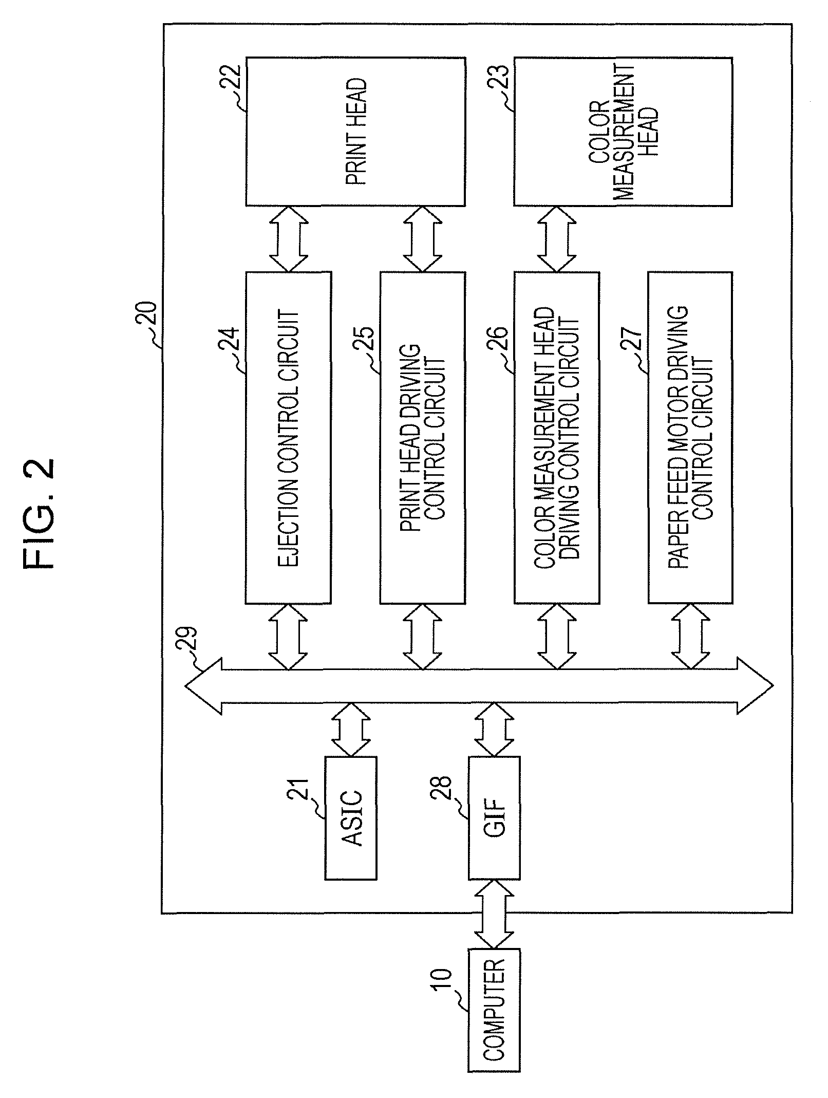
[0008]According to an aspect of the invention, a printing apparatus is adapted to form a printed image by forming a plurality of ink dots based on an ink amount specified for each of a plurality of pixels forming image data. The printing apparatus includes a determination unit, a patch printing unit, a color measurement unit, a correction data creation unit and a printing unit. The determination unit is configured to analyze the image data and to determine at least one color patch to be printed based on a result of the analysis. The patch printing unit is configured to print the at least one color patch. The color measurement unit is configured to perform color measurement on the at least one color patch to obtain a color value indicated in the at least one color patch. The correction data creation unit is configured to create correction data using the color value obtained by the color measurement unit. The printing unit is configured to form the ink dots based on the ink amount that has been corrected based on the correction data. In this manner, the color patch to be formed is determined based on the result of analyzing the image data to be printed, and thus it is possible to prevent the printing of excessive color patches and carry out calibration efficiently.
[0009]Moreover, it is preferable to form the color patch using a frequently-used ink that is used more often than other inks in the printing of the image data performed by the printing unit. This is because if the accuracy with respect to the inks that are used more frequently in the printing of the image data can be improved, the overall reproduction accuracy of the image data can be improved efficiently. Furthermore, it is preferable to form the color patch based on a frequently-appearing ink amount that is an ink amount appearing more frequently among ink amounts specified for each of the pixels in the image data. This, too, is because if the accuracy with respect to the ink amounts that are used more frequently in the printing of the image data can be improved, the overall reproduction accuracy of the image data can be improved efficiently.
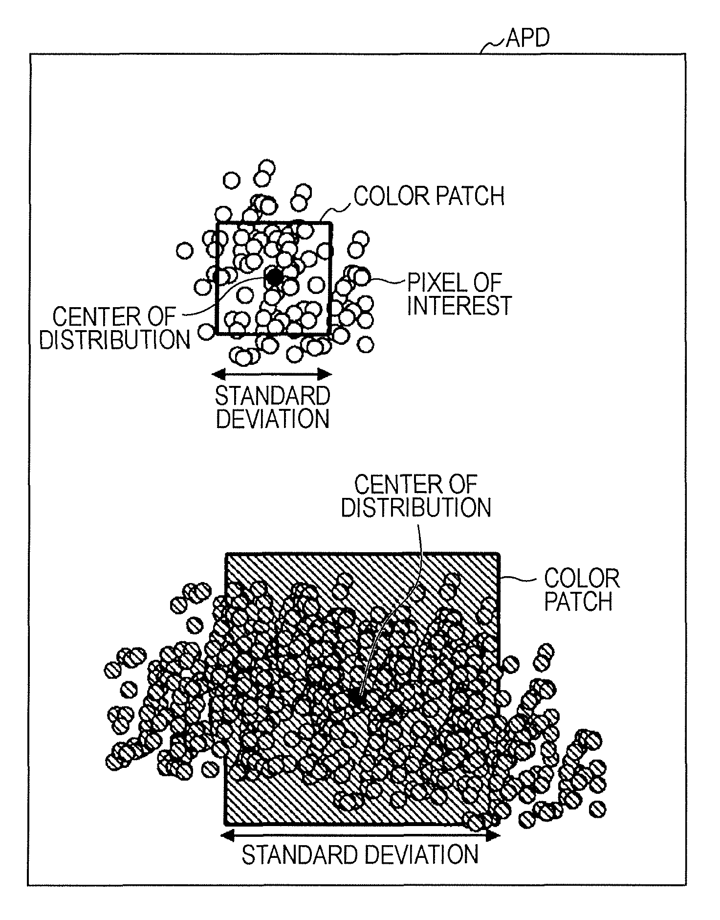
[0010]Moreover, the location and size of the color patch may be determined based on the result of the analysis in addition to the color of the color patch. In other words, the location, size, and so on of the color patch to be printed may be determined based on a spatial distribution state of the pixels in the image data. Basically, it is desirable to form the color patch in a region in which the pixels of an ink amount corresponding to the color patch are heavily distributed, and it is desirable to form the color patch at a large size in the case where the pixels of an ink amount corresponding to the color patch are widely distributed. If the color patch is formed at a large size, the distribution range of color measurement points in the color patch can be increased.
[0011]In addition, the color patch may be determined based on a history of the color patches printed in the past in addition to the results of analyzing the image data. Accordingly, a recording medium that stores the color patches that have been printed by the printing unit in the past and history data that holds the color values obtained by performing color measurement on the color patches is also provided. By referring to the history data, it is determined that a different color patch than the color patch printed in a last printing cycle by the patch printing unit is to be printed. This makes it possible to prevent forming the same color patch in succession. The correction data creation unit creates the correction data by integrating the color values held in the history data with the color values obtained by performing color measurement on the different color patches than the color patches printed in the past. In other words, the correction data is created based on the color measurement values of a color patch printed in multiple periods of time. Doing so makes it possible to reduce the number of color patches printed in each period of time, and thus makes it possible to implement faster printing. Meanwhile, a case in which the image data is not characteristic can also be considered. In such a case, it is desirable to preferentially form color patches based on the history data.

Problems solved by technology

Accordingly, some users have felt that the time required for calibration is too long, whereas other users have felt that the accuracy they desire cannot be achieved.
There has also been a problem in that various color patches of colors unrelated to the colors expressed by an image that is to be printed are formed, and thus the accuracy of the colors expressed by the image that is to be printed cannot be ensured.

Method used


Image

  • Printing apparatus and calibration method
  • Printing apparatus and calibration method
  • Printing apparatus and calibration method

Examples


Embodiment Construction

[0029]Hereinafter, an embodiment of the invention will be described according to the following order: 1. Configuration of Calibration Apparatus and Printing Apparatus; 2. Printing Process; 3. Setting Process; and 4. Modified Embodiments.

1. Configuration of Calibration Apparatus and Printing Apparatus

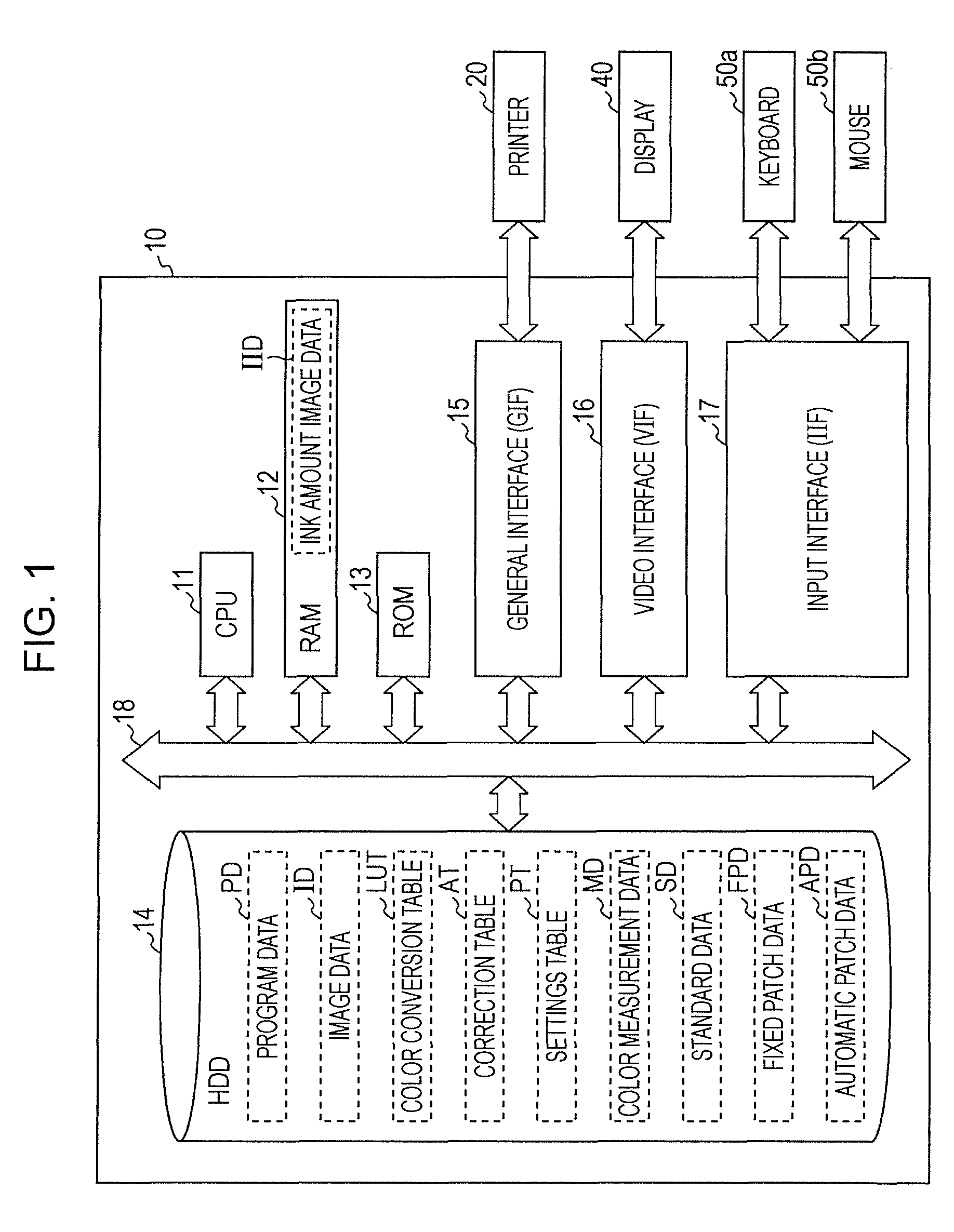
[0030]FIG. 1 is a block diagram illustrating the configuration of the computer that executes a profile creation method according to an embodiment of the invention. In FIG. 1, a computer 10 is configured of a CPU 11, a RAM 12, a ROM 13, a hard disk drive (HDD) 14, a general interface (GIF) 15, a video interface (VIF) 16, an input interface (IIF) 17, and a bus 18. The bus 18 implements data communication among the various constituent elements 11 through 17 of which the computer 10 is configured, and controls the communication using a chipset or the like (not shown). Program data PD for executing various types of programs including an operating system (OS) is stored in the HDD 14, and the C...


PUM


Abstract

A printing apparatus is adapted to form a printed image by forming ink dots based on an ink amount specified for each of a plurality of pixels forming image data. The determination unit is configured to analyze the image data and to determine at least one color patch to be printed based on a result of the analysis. The patch printing unit is configured to print the color patch. The color measurement unit is configured to perform color measurement on the color patch to obtain a color value indicated in the color patch. The correction data creation unit is configured to create correction data using the color value obtained by the color measurement unit. The printing unit is configured to form the ink dots based on the ink amount that has been corrected based on the correction data.

Description

CROSS-REFERENCE TO RELATED APPLICATIONS[0001]This application claims priority to Japanese Patent Application No. 2009-227535 filed on Sep. 30, 2009. The entire disclosure of Japanese Patent Application No. 2009-227535 is hereby incorporated herein by reference.BACKGROUND[0002]1. Technical Field[0003]The present invention relates to printing apparatuses and calibration methods, and particularly relates to a printing apparatus that forms a printed image by forming ink dots based on ink amounts specified for each pixel of which image data is configured, and to a calibration method for such a printing apparatus.[0004]2. Related Art[0005]A calibration method in which, when executing calibration, a user sets desired environment information that he / she feels is optimal has been proposed (see JP-A-2001-213036).SUMMARY[0006]In calibration, increasing the number of color patches (color control patches) that are printed / measured generally makes it possible to attain a higher degree of accuracy...

Claims


Application Information

Patent Timeline
IPC IPC(8): G06F15/00
CPCH04N1/00015H04N1/00034H04N1/00045H04N1/62H04N1/00087H04N1/6033H04N1/0005
Inventor HOSHII, JUN
Owner SEIKO EPSON CORP
Learn More