
Dual-Mode Extended Depth-of-Field Imaging Systems

Inactive Publication Date: 2011-03-31
RICOH KK
View PDF13 Cites 8 Cited by
  • Summary
  • Abstract
  • Description
  • Claims
  • Application Information

AI Technical Summary

Benefits of technology

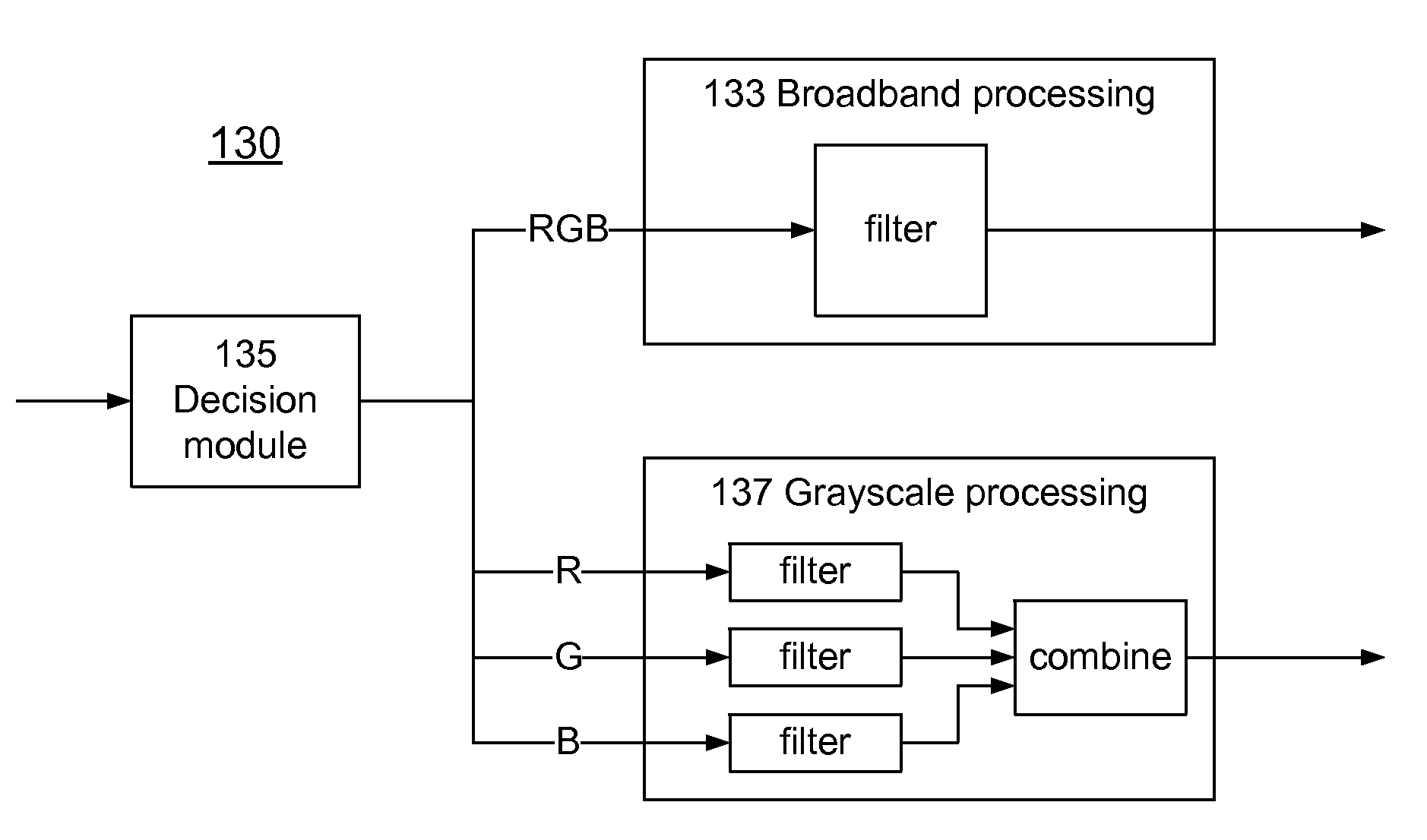
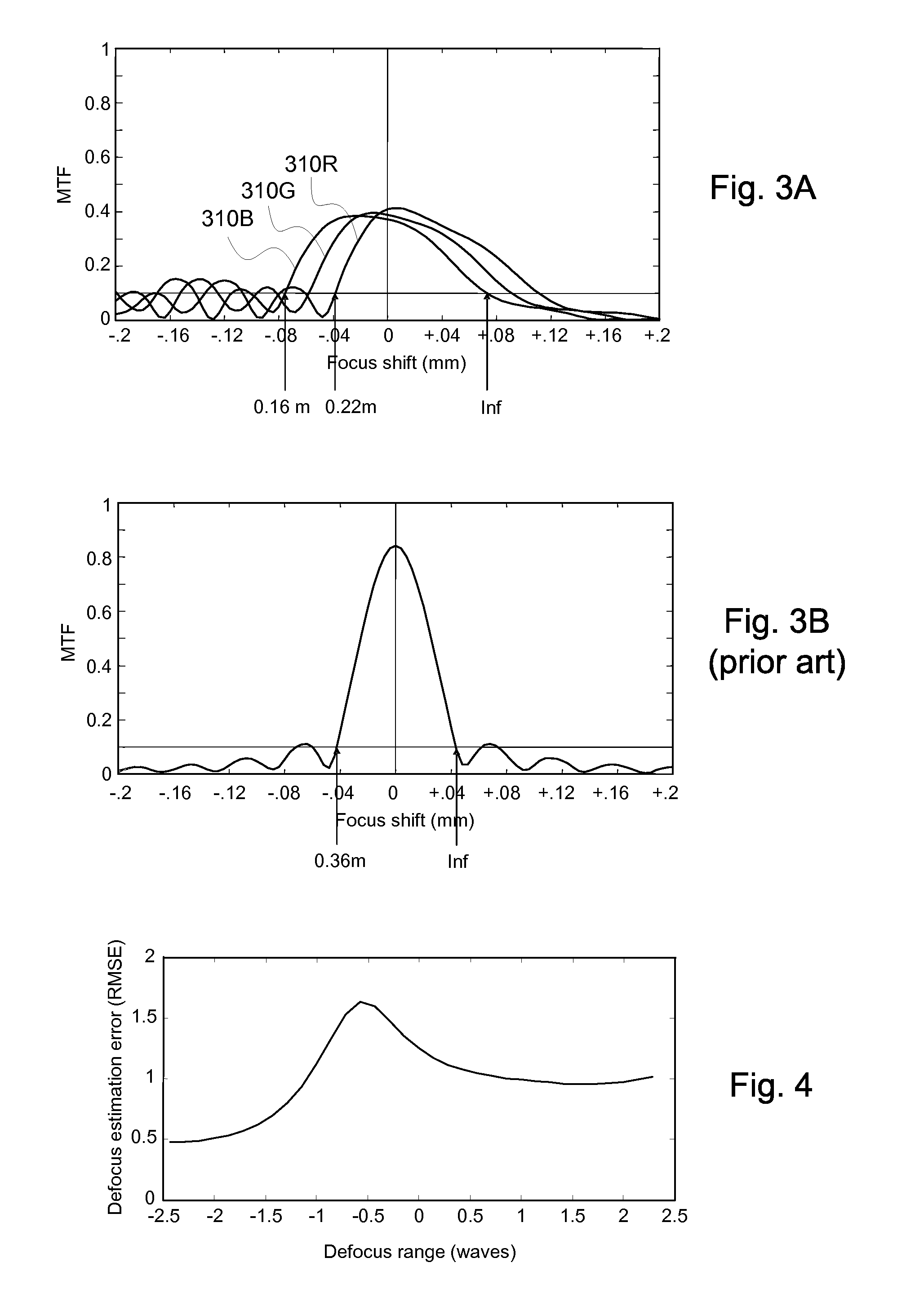
[0009]The present invention overcomes the limitations of the prior art by providing a digital-optical imaging system that can be operated in two modes, which shall be referred to as broadband mode and grayscale mode. In broadband mode, different color images are captured and then image processed together. The optics is intentionally aberrated to increase the depth of field, with the image processing compensating for the aberrations. In grayscale mode, the different color images are captured and then image processed separately. The color images are assumed to be correlated so that it is not necessary to have clear images of all color channels. Accordingly, the optics are designed so that the different color images focus at different locations, thus increasing the range over which at least one color image is in focus. The two modes impose opposite requirements on the optics. In broadband mode, the optics ideally is designed so that all color channels behave approximately the same, focusing at approximately the same point. In grayscale mode, the optics ideally is designed so that all color channels behave differently, with each color channel focusing at a different point. The optics is designed to balance these two opposing requirements.

Problems solved by technology

In such applications, the dispersion found in optical glasses and plastics makes it difficult to focus all wavelengths at the same point.
However, the resulting lens designs can be relatively complex and expensive.
That is, the full color image is always somewhat blurry but does not get significantly better or worse as the location of the image plane changes.
However, one major drawback is that the image is always somewhat blurry.
Another drawback is that the system must still be designed so that all color channels are at least moderately in focus.
However, this approach is limited to this special class of objects and such a system would not be able to acceptably image a color image where the different color channels were uncorrelated, because some of the color channels will always be unacceptably out of focus.

Method used


Image

  • Dual-Mode Extended Depth-of-Field Imaging Systems
  • Dual-Mode Extended Depth-of-Field Imaging Systems
  • Dual-Mode Extended Depth-of-Field Imaging Systems

Examples


Embodiment Construction

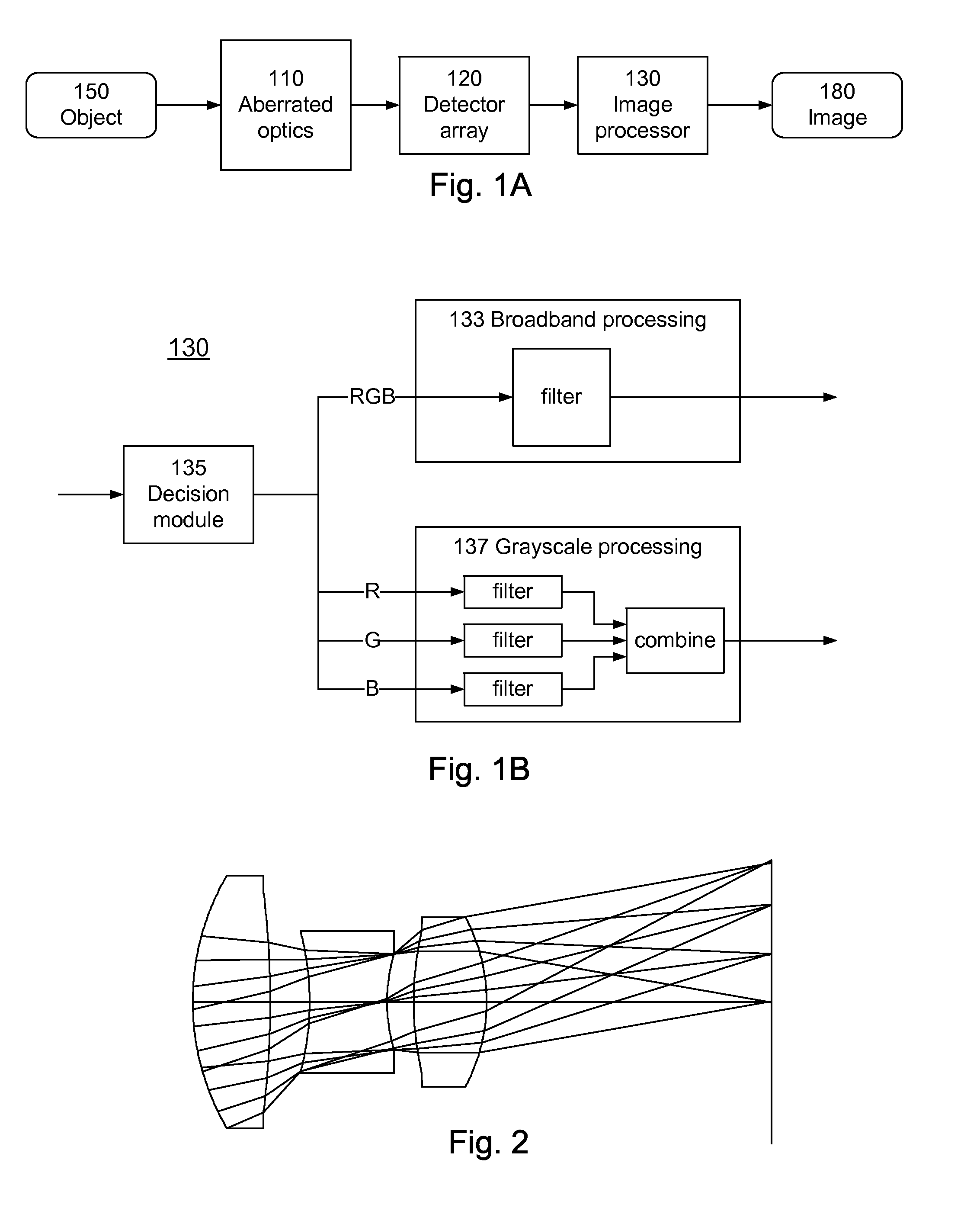
[0021]FIG. 1 is a block diagram of a digital-optical imaging system according to the invention. The imaging system includes an optics module 110 (e.g., a lens assembly), a detector module 120 (e.g., CCD detector array) and an image processing module 130 (e.g., typically implemented in dedicated chips or software). As shown in FIG. 1B, the image processing module 130 can be operated in two different modes, which shall be referred to as broadband mode 133 and grayscale mode 137. A decision module 135 switches between the two modes. The imaging system produces a digital image 180 of an object 150.

[0022]The imaging system is “digital-optical” in the sense that optics 110 produces an optical image, but the optical image is not high quality. Instead, for reasons described below, the optical module 110 is intentionally aberrated, which results in a degraded optical image. The degraded optical image is captured by the detector array 120, and the captured image is digitally processed by the ...


PUM


Abstract

A digital-optical imaging system can be operated in two modes, which shall be referred to as broadband mode and grayscale mode. In broadband mode, different color images are captured and then image processed together. The optics are intentionally aberrated to increase the depth of field, with the image processing compensating for the aberrations. In grayscale mode, the different color images are captured and then image processed separately. The color images are assumed to be correlated so that it is not necessary to have clear images of all color channels. Accordingly, the optics are designed so that the different color images focus at different locations, thus increasing the overall depth of field where at least one color image is in focus.

Description

BACKGROUND OF THE INVENTION[0001]1. Field of the Invention[0002]This invention relates to imaging systems in which specifically aberrated optics are balanced by specific digital image processing.[0003]2. Description of the Related Art[0004]Electro-optic imaging systems typically include optics (e.g., a lens assembly), detectors (e.g., CCD detector array) and digital image processing (e.g., typically implemented in dedicated chips or software). In many imaging applications, the objects of interest have many spectral components. Traditionally, the optical designer optimizes the lens design parameters to minimize a variety of optical aberrations so as to produce a high quality optical image at a single image plane. Applications involving imaging of spectrally broad sources require that these aberrations be minimized over a range of wavelengths dependent on the spectral sensitivity of the detector. In such applications, the dispersion found in optical glasses and plastics makes it diffi...

Claims


Application Information

Patent Timeline
IPC IPC(8): H04N5/335H04N5/225
CPCG02B27/0075H04N5/3572H04N5/23229H04N5/217H04N23/81H04N23/80H04N25/615H04N25/61
Inventor ROBINSON, M. DIRKSTORK, DAVID G.
Owner RICOH KK
Learn More