
Apparatus and method for electronic access control

a technology of electronic access control and apparatus, applied in the field of electronic access control system, can solve the problems of content spilling out of the drawer or enclosure, no design generally encompassing all of the desired characteristics, etc., and achieve the effect of efficient upgrad

Active Publication Date: 2011-03-31
COMPX INTERNATIONAL
View PDF96 Cites 37 Cited by
  • Summary
  • Abstract
  • Description
  • Claims
  • Application Information

AI Technical Summary

Benefits of technology

"The present patent text describes an improved electronic lock system for secure enclosures that uses a microprocessor-based access control circuit and a master-slave control system. The system includes a user interface for adjusting system parameters and a battery-operated power supply for the access control circuit. The system also includes motion sensors to detect movement of the enclosure and a communications module for uploading inventory data to a central server. The technical effects of the patent text include improved security control, efficient management of inventory, and enhanced user experience."

Problems solved by technology

When such mobile enclosures are being moved from one location to another, an unsecured door or drawer located in the enclosure may come open, causing the contents of the drawer to spill out of the drawer or enclosure or causing injury.
Additionally, there can also be a need to sense a variety of undesirable conditions for the various components of the electronic access control system, such as, for example, low battery conditions, unauthorized entry conditions, or failure to check in or communicate over the network conditions.
While various implementations of electronic access control systems including one or more electronic locks have been developed, no design has emerged that generally encompasses all of the desired characteristics as hereafter presented in accordance with the subject technology.

Method used


Image

  • Apparatus and method for electronic access control
  • Apparatus and method for electronic access control
  • Apparatus and method for electronic access control

Examples


Embodiment Construction

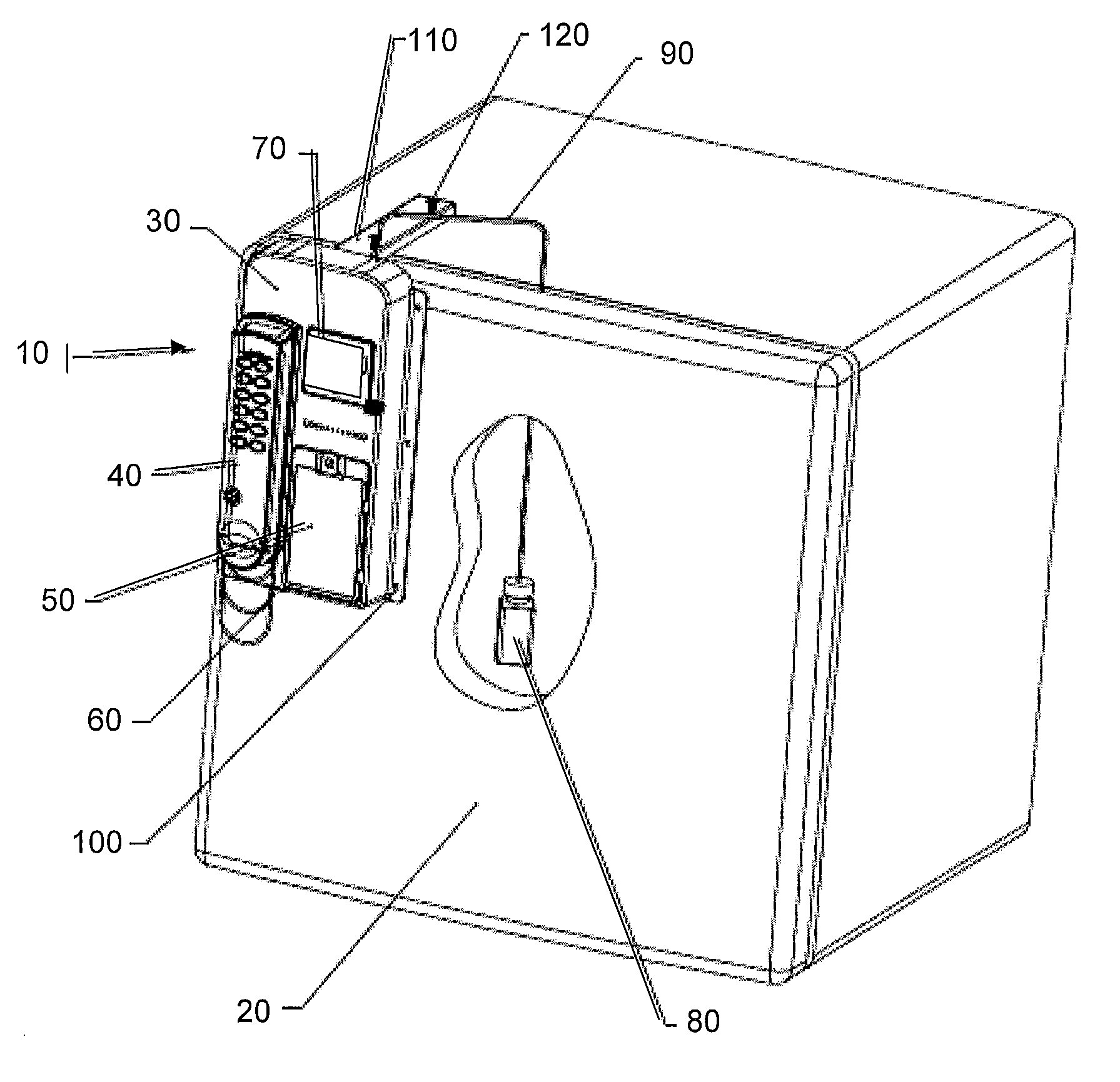
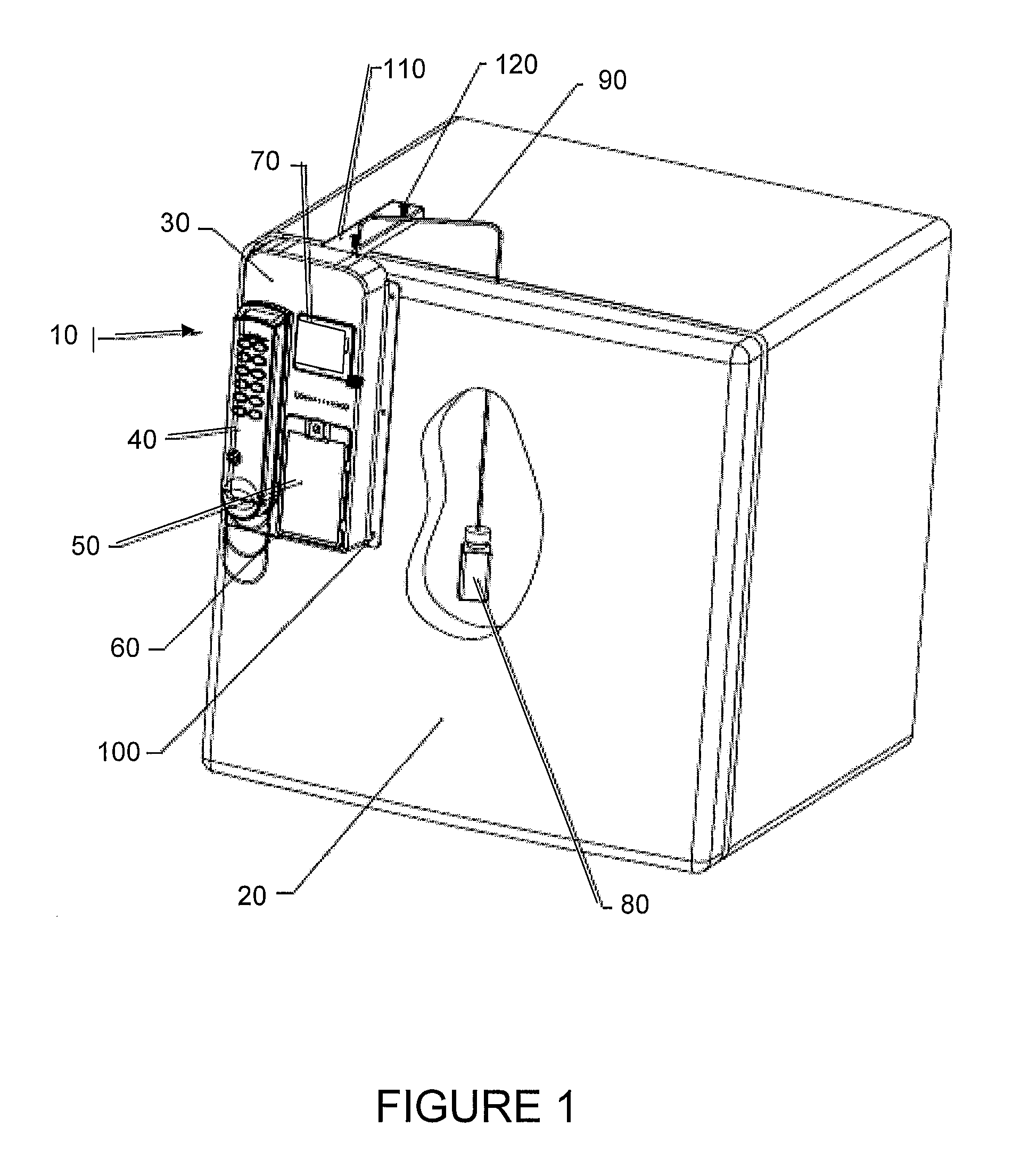
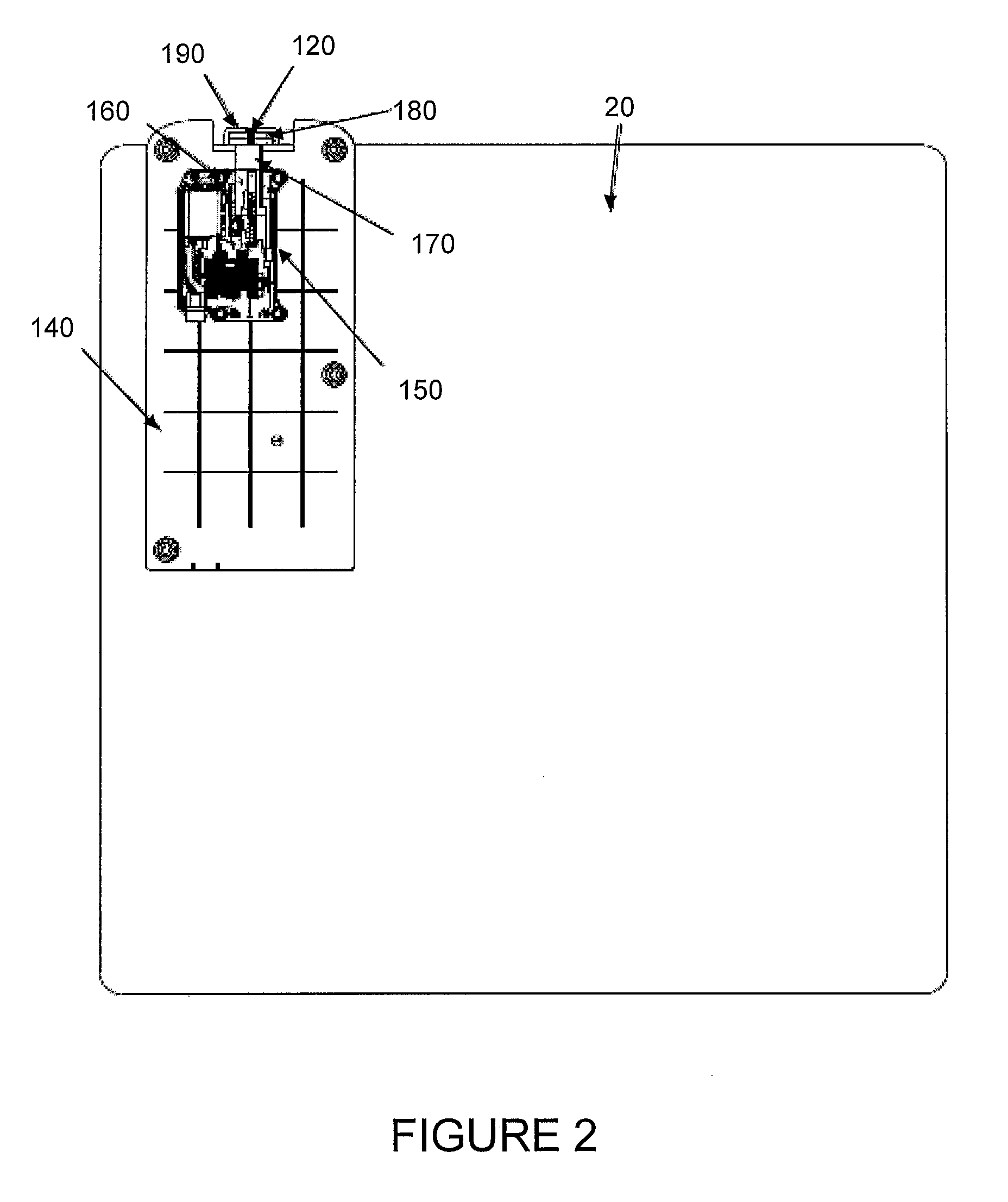
[0059]As discussed in the Summary of the Invention section, the present subject matter is concerned with electronically controlled access control systems.

[0060]Selected combinations of aspects of the disclosed technology correspond to a plurality of different embodiments of the present subject matter. It should be noted that each of the exemplary embodiments presented and discussed herein should not insinuate limitations of the present subject matter. Features or steps illustrated or described as part of one embodiment may be used in combination with aspects of another embodiment to yield yet further embodiments. Additionally, certain features may be interchanged with similar devices or features not expressly mentioned which perform the same or similar function.

[0061]It should be specifically noted that while the present disclosure generally describes the lock disclosed herein as a retrofittable lock, such terminology should not be taken as a limitation of the present subject matter...


PUM


Abstract

Apparatus and methodology for providing electronic access control are disclosed. In an exemplary configuration, a retrofittable electronic lock can be used to provide secure storage to an enclosure. A user interface and LCD visual display can be provided to permit convenient adjustment of system operational parameters. In certain embodiments, the electronic access control system includes master-slave control capabilities. In other embodiments, the electronic access control system includes inventory management capability. In still other embodiments, apparatus and methodologies provide the secure storage of the enclosure when the enclosure is being moved or otherwise transported from one location to another location. Various alternative arrangements may provide various alert features, as well as battery features which facilitate rapid replacement and / or reconfiguration.

Description

PRIORITY CLAIM[0001]This application claims the benefit of previously filed U.S. Provisional Patent Application entitled “APPARATUS AND METHOD FOR ELECTRONIC ACCESS CONTROL,” assigned U.S. Ser. No. 61 / 246,602, filed Sep. 29, 2009, and which is incorporated herein by reference for all purposes.FIELD OF THE INVENTION[0002]The present subject matter generally relates to lock or access control systems, and more particularly to electronically controlled lock systems such as may be applied to various storage enclosures or cabinets to provide secure storage of various items, equipment, materials, and / or information within the enclosures or cabinets. More specifically, certain present aspects may relate to master-slave control for a plurality of electronic locks used in an electronic access control system, to inventory management using electronic locks, and / or to electronic locks with various features including LCD display screens, motion sensor controls, and alert capabilities.BACKGROUND O...

Claims


Application Information

Patent Timeline
Patent Type & Authority Applications(United States)
IPC IPC(8): G06F7/04
CPCG06Q10/087G07C1/32G07C9/00166G07C9/00563G07C2009/0092G07C9/00817G07C9/00896G07C2009/00642G07C9/00571G07C9/38
Inventor KACZMARZ, KENNETH A.PAYSON, JOHN B.GARLISCH, JOHN A.ROBINSON, BROCK E.MAVROMATIS, JESSEMLYNARCZYK, MITCHELL S.
Owner COMPX INTERNATIONAL
Learn More