
Cognitive communication network system and communicating method thereof

a communication network and network system technology, applied in the field of cognitive communication network system, can solve the problems of difficult development of general-purpose devices that manage reconfiguration, different functions of devices, and inability to make common interfaces between devices, etc., and achieve the effect of more efficient reconfiguration processing

Active Publication Date: 2011-03-24
NAT INST OF INFORMATION & COMM TECH
View PDF0 Cites 60 Cited by
  • Summary
  • Abstract
  • Description
  • Claims
  • Application Information

AI Technical Summary

Benefits of technology

The present invention is about a cognitive communication network system that can dynamically switch between different types of wireless networks and optimize network efficiency. This system can collect information about available networks and change the way it connects to these networks in real-time, ensuring the best use of network resources and improving overall throughput and capacity. The invention also includes a software wireless device that can support multiple frequencies and wireless methods by switching between them. The technical effects of this invention include improved efficiency and flexibility in utilizing various radio access systems, seamless handover, and improved user experience.

Problems solved by technology

Thus, functions in the device are different and interfaces between the devices cannot be made common.
For this reason, it has been difficult to develop a general-purpose device that manages reconfiguration of various types of radio access devices.
However, it relates to connection or disconnection of the wireless link and collection of wireless information and is not intended to optimize the radio access network.

Method used


Image

  • Cognitive communication network system and communicating method thereof
  • Cognitive communication network system and communicating method thereof
  • Cognitive communication network system and communicating method thereof

Examples


Embodiment Construction

[0074]An embodiment of the present invention will be described below referring to an embodiment shown in the attached drawings. The embodiment is not limited to the following.

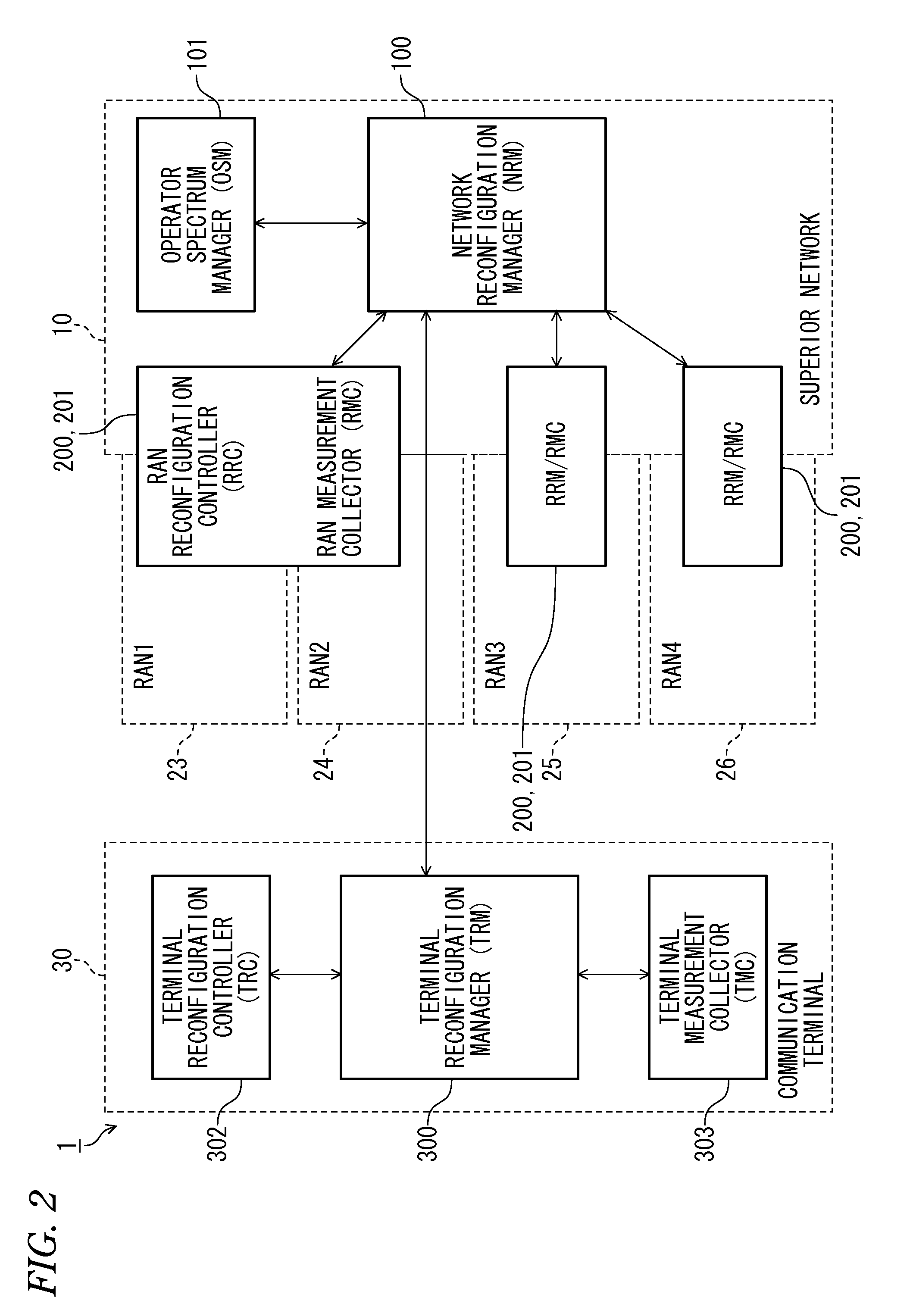
[0075]FIG. 1 is a configuration diagram illustrating a specific example of a cognitive communication network system (1) according to the present invention. In the cognitive communication network, a communication network is constituted by a superior communication network (10), which is a packet-based network, and a plurality of radio access networks (20), (21), and (22) to which the superior communication network (10) provides a common platform. Then, a cognitive communication terminal (hereinafter referred to as a communication terminal) (30) connected to the radio access network is connected to the superior communication network (10). The superior communication network is assumed to be an IP network such as the Internet, for example.

[0076]In the cognitive communication network, in addition to the wireless LAN ...


PUM


Abstract

Object: To provide a mechanism and a function of a system that can determine a communication method and the like effectively utilizing frequency resources, considering priority of each communication, in a cognitive communication network system of a frequency shared type or the like assuming that a given frequency band is shared by a plurality of systems in use.Solution: In a configuration in which a cognitive communication network system has a plurality of radio access networks 23 and a superior communication network 10 that provides a common platform at least to the radio access networks, in a plurality of base stations 23a on at least a part of the radio access network 23, base-station state obtaining means 232 that collect information relating to a state of the base station itself in the base station or a communication state and base-station communication reconfiguration managing means 231 that reconfigure at least one of either a selection of the base station to be used in the communication or a communication condition in the base station on the basis of the information collected by the base-station state obtaining means are provided.

Description

TECHNICAL FIELD[0001]The present invention relates to a cognitive communication network system in which communication terminals communicate with each other, while presence of connection with a plurality of wired or wireless communication networks or a connecting method is dynamically reconfigured, and a communicating method thereof; particularly to a system configuration for reconfiguring communication in each communication network.BACKGROUND ART[0002]Various radio access systems including mobile phones, wireless LANs, PHS and the like have spread and wireless MAN services such as WiMAX (Worldwide Interoperability for Microwave Access) (registered trademark) have started. In order to effectively utilize such access systems, research and development of a technology that hands over a different type of wireless network in a seamless manner has progressed (See Non Patent Documents 1 and 2).[0003]Also, as disclosed in Non Patent Document 3, a software wireless technology capable of conne...

Claims


Application Information

Patent Timeline
Patent Type & Authority Applications(United States)
IPC IPC(8): H04L12/28H04W4/00
CPCH04L5/0032H04L5/0035H04L5/0064H04B7/005H04W24/00H04W48/10H04W48/18H04L5/0092
Inventor ISHIZU, KENTAROMURAKAMI, HOMAREMIYAMOTO, GOHTRAN, HA NGUYENFILIN, STANISLAVSUN, CHENDEMESSIE, YOHANNES ALEMSEGEDHARADA, HIROSHI
Owner NAT INST OF INFORMATION & COMM TECH
Learn More