
Nanostructure-Enhanced Platelet Binding and Hemostatic Structures

Inactive Publication Date: 2011-03-17
NANOSYS INC
View PDF99 Cites 59 Cited by
  • Summary
  • Abstract
  • Description
  • Claims
  • Application Information

AI Technical Summary

Benefits of technology

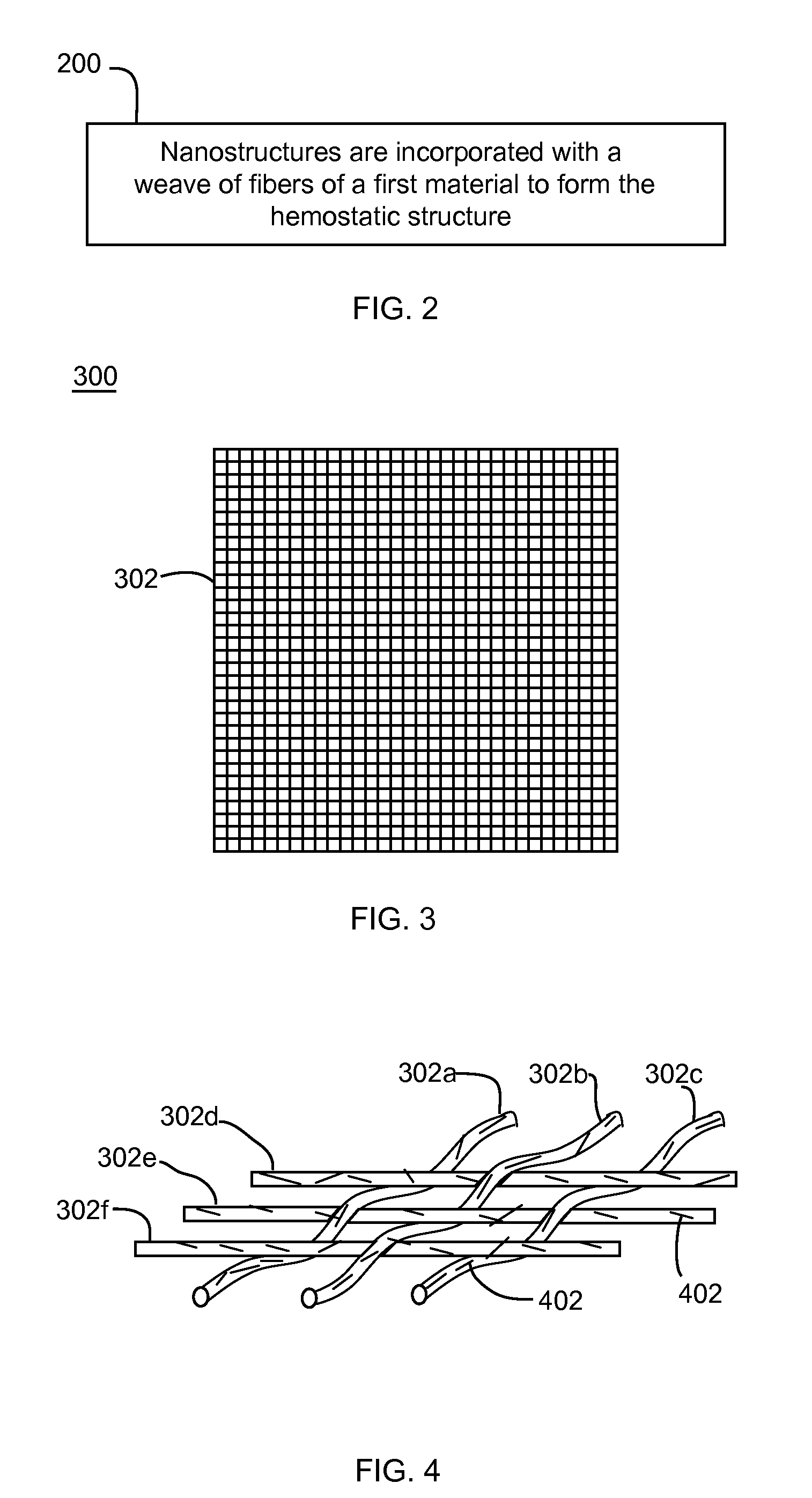
[0014]In a first aspect of the present invention, a hemostatic structure is provided. The hemostatic structure includes a base structure. The base structure may have a variety of forms, including that of a woven material (e.g., weave of fibers) or nonwoven material, The hemostatic structure further includes nanostructures incorporated with the base structure (e.g., a coating of nanostructures on the base structure, a mixing of nanostructures with the material of the base structure, etc.). The nanostructures are configured to induce platelet binding and efficient hemostasis when the hemostatic structure is contacted with blood. Upon binding to the nanostructure surfaces, platelets become activated and provide a surface that accelerates thrombin-induced cleavage of fibrinogen (thrombin burst), enhancing the overall rate and strength of clot formation.

Problems solved by technology

Such bandage based materials are typically not inherently hemostatic, functioning more as absorbers of blood and leading to a plugging of a wound.
Such products suffer from cost and stability issues that limit their use.
Such bulk hemostats have disadvantages.
For example, such existing bulk hemostats do not function as quickly as desired, may be difficult to apply, and not all existing bulk hemostats can be absorbed by the human body.
Static blood may be entrapped within pores of the material, and the entrapped blood subsequently clots due to stasis.
However, such a technique would be expensive.
However, such a method of inducing hemostasis is not typical of the physiologically relevant response whereby an activated surface triggers the intrinsic coagulation pathway and also leads to enhanced platelet binding.
However, these approaches suffer from certain drawbacks such as poor absorptivity of the scaffold material to which they are applied.

Method used


Image

  • Nanostructure-Enhanced Platelet Binding and Hemostatic Structures
  • Nanostructure-Enhanced Platelet Binding and Hemostatic Structures
  • Nanostructure-Enhanced Platelet Binding and Hemostatic Structures

Examples


example hemostatic bandage embodiments

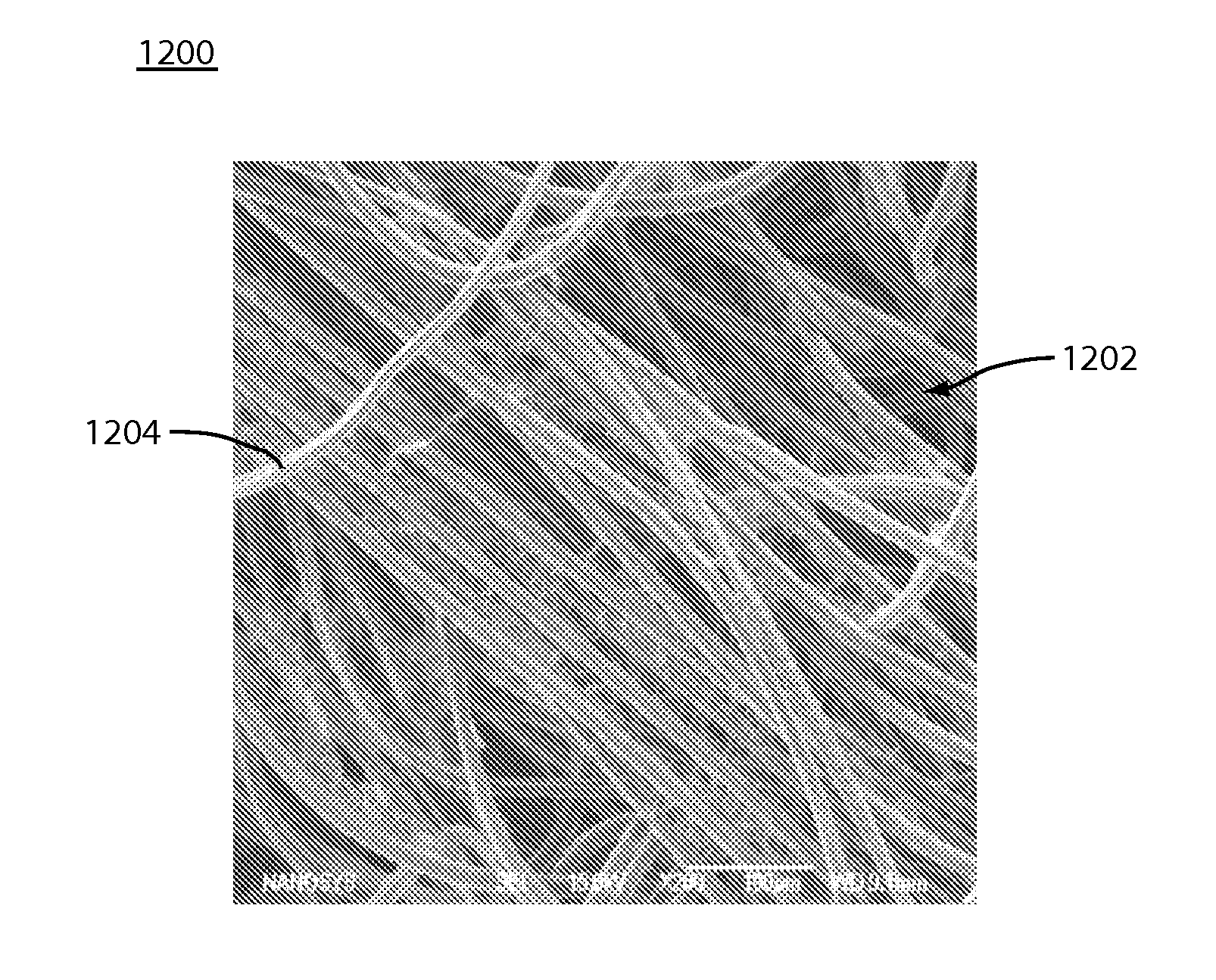
[0099]In an embodiment, nanostructures, such as inorganic silica nanofibers, are applied onto the surface of bandages / bandage fibers. Such nanostructures (e.g., nanofibers, nanoparticles, etc.) assist in activating the intrinsic (contact) clotting cascade, leading to the slowdown or stoppage of bleeding. The dimensions of the nanostructures are such that they provide an excellent surface for activation of the contact pathway, and thus provide a non-biological way of enhancing clotting on bandage surfaces. Such nanostructures may be nanowires, nanofibers, nanoparticles, and / or any other nanostructure type described herein. Such nanostructures may be made of silicon, silicon having a thin oxide layer, silica, potassium (including potassium nanofibers, nanowires, or nanoparticles), silicon nanostructures functionalized with potassium (e.g., silicon nanofibers functionalized with potassium), etc.

[0100]In example embodiments, bandage materials that may be coated and / or otherwise enhanced...

example expandable

and Absorbent Hemostatic Material Embodiments

[0128]Expandable polymers have been used for wound closure to prevent blood loss after endoscopic surgery where the entry / exit point of the endoscopic device is through a blood vessel. An example of such device is the Angioseal™ vascular closure device sold by St. Jude Medical of St. Paul, Minn. Absorbent materials, such as cotton gauze or tampon structures, have also been used for wound closure. In a device using an expandable material, blood and / or other fluids are absorbed by the material, and the material swells to cause a physical barrier. Static blood may be entrapped within pores of the material, which clots due to stasis. It would be advantageous if the blood within the expanded material could be made to clot more rapidly. Embodiments of the present invention enable an increased rate of clotting for devices based on expandable materials and non-expandable materials (e.g., cotton-based, such as gauze, tampon, and other such non-exp...

embodiments

Example Hemostatic Material Embodiments

[0136]Various materials have been developed to help stop wounds from bleeding excessively and to increase a rate of clotting. Such materials may be used in surgical procedures and / or by first responders to traumatic events, for example. Existing bulk hemostats have disadvantages, however. For example, it would advantageous if existing bulk hemostats functioned more quickly, were resorbable, and / or did not have an exothermic reaction with blood. Embodiments of the present invention overcome these limitations of conventional bulk hemostats.

[0137]In an embodiment, nanostructures, such as nanofibers, are co-formulated with glass microspheres (either solid or porous). This co-formulated material has an enhanced hemostatic activity that is not purely additive—i.e., the combination of the nanostructures and glass microspheres has a faster hemostatic activity (e.g., when measured in a TEG) than the nanostructures or glass microspheres alone, which is n...


PUM

PropertyMeasurementUnit
Structureaaaaaaaaaa
Densityaaaaaaaaaa
Adhesion strengthaaaaaaaaaa

Abstract

Methods, systems, and apparatuses for nanomaterial-enhanced platelet binding and hemostatic medical devices are provided. Hemostatic materials and structures are provided that induce platelet binding, including platelet binding and the coagulation of blood at a wound / opening caused by trauma, a surgical procedure, ulceration, or other cause. Example embodiments include platelet binding devices, hemostatic bandages, hemostatic plugs, and hemostatic formulations. The hemostatic materials and structures may incorporate nanostructures and / or further hemostatic elements such as polymers, silicon nanofibers, silicon dioxide nanofibers, and / or glass beads into a highly absorbent, gelling scaffold. The hemostatic materials and structures may be resorbable.

Description

[0001]This application is a continuation-in-part of U.S. patent application Ser. No. 12 / 329,431, filed on Dec. 5, 2008, which claims the benefit of U.S. Provisional Application No. 60 / 992,827, filed on Dec. 6, 2007, and U.S. Provisional Application No. 60 / 992,865, filed on Dec. 6, 2007, the entire contents of which are hereby incorporated by reference.STATEMENT REGARDING FEDERALLY SPONSORED RESEARCH OR DEVELOPMENT[0002]This invention was made with government support under Contract No. N00014-07-C-0008 awarded by the Office of Naval Research. The government may have certain rights in the invention.BACKGROUND OF THE INVENTION[0003]1. Field of the Invention[0004]The present invention relates to hemostatic materials incorporating various structures, such as nanostructures. The invention further relates to highly absorbent scaffold materials with hemostatic materials incorporated therein. The present invention further relates to materials incorporating nanostructures for enhanced platele...

Claims


Application Information

Patent Timeline
IPC IPC(8): A61K9/70A61K33/00A61K9/00A61P7/04A61L33/00B82Y5/00
CPCA61B17/0057A61B17/064D06M23/08D06M11/79A61L2400/12A61L2400/04A61L24/08A61L24/02A61L15/28A61B2017/00601A61B2017/00884A61B2017/00893A61F13/00008A61F13/00034A61F13/00991A61F13/36A61F2013/00238A61F2013/00472A61L15/18C08L5/04C08L1/26A61P7/04A61F13/01008A61F13/01034
Inventor DANIELS, R. HUGHLI, ESTHERROGERS, ERICA J.
Owner NANOSYS INC
Learn More