
Feedwell for a gravity separation vessel

Inactive Publication Date: 2011-03-17
SYNCRUDE CANADA LTD
View PDF9 Cites 23 Cited by
  • Summary
  • Abstract
  • Description
  • Claims
  • Application Information

AI Technical Summary

Benefits of technology

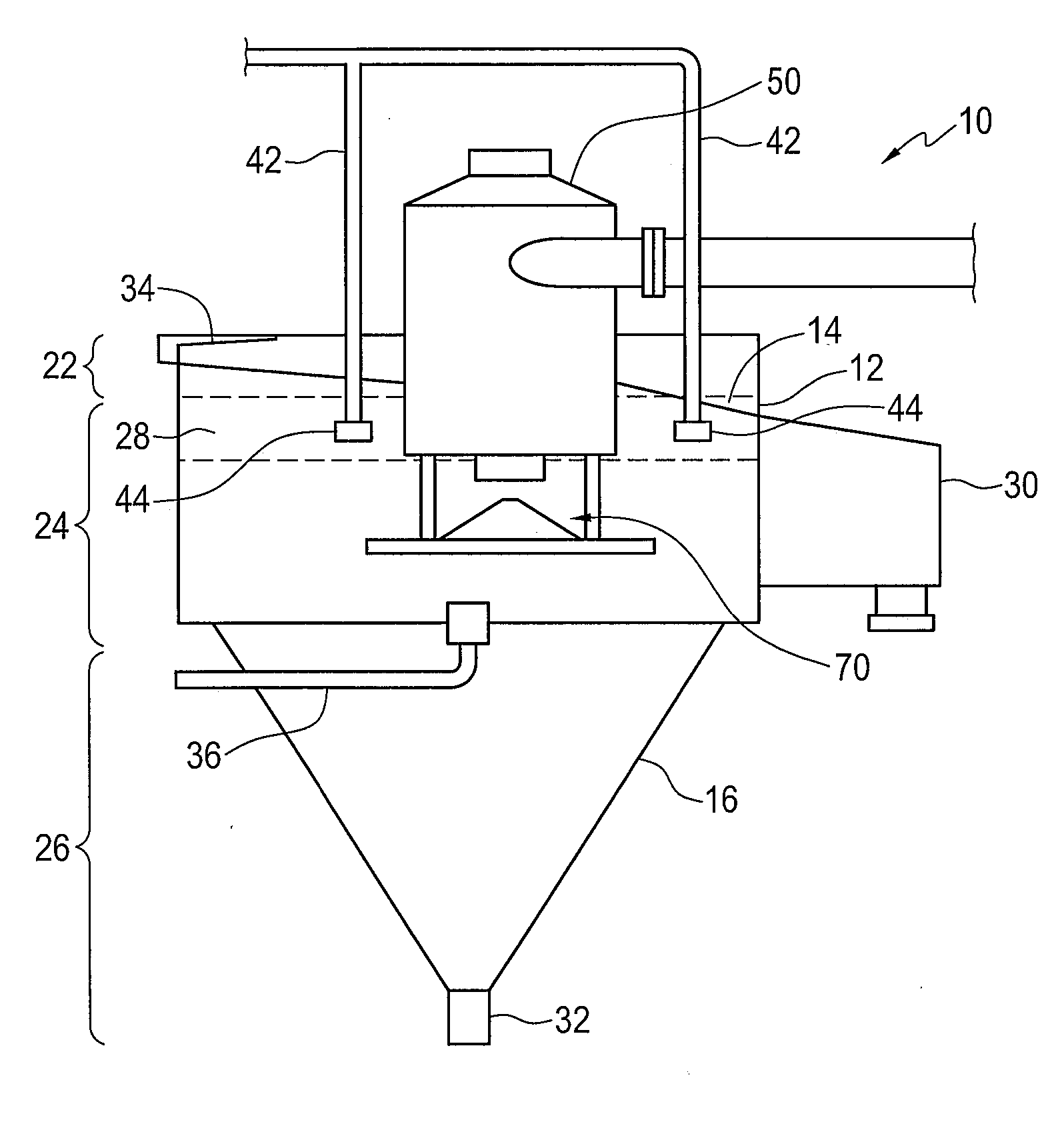
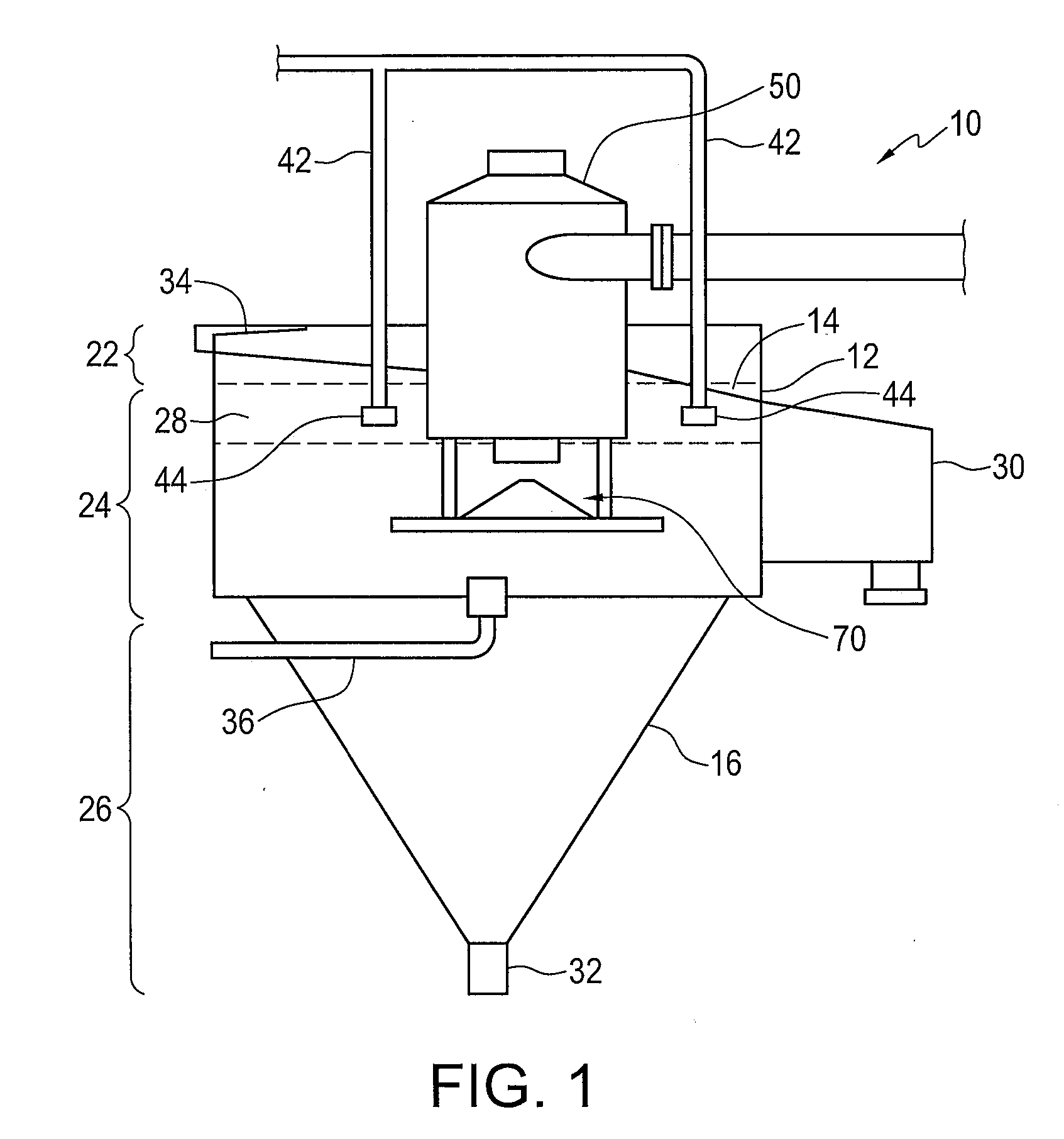
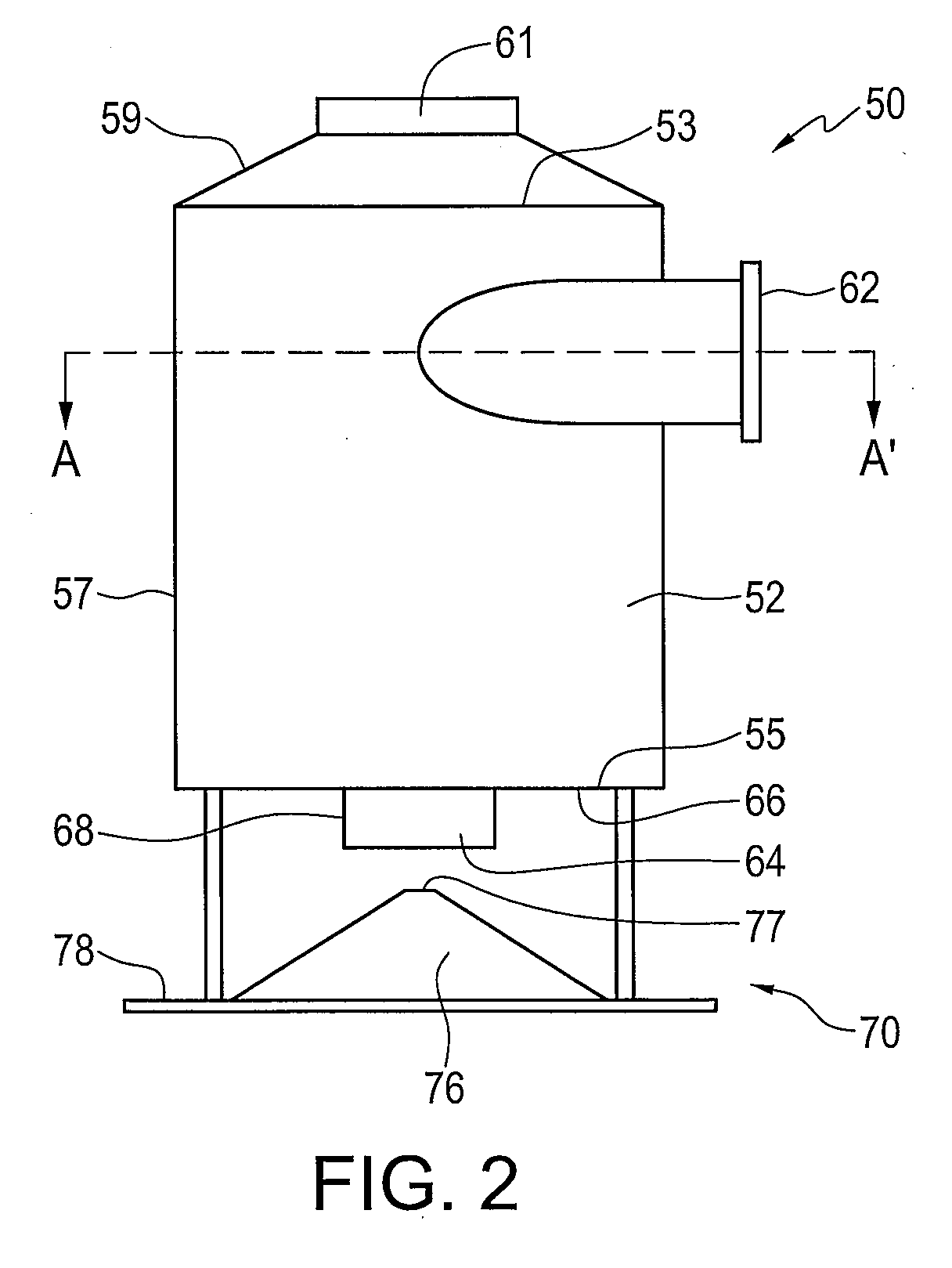
[0007]In a first aspect, a feedwell for use in a gravity separation vessel which provides more uniform distribution in the vessel as the influent stream enters the vessel for separation is provided. The feedwell comprises: a walled member having an upper perimeter edge, a lower perimeter edge and a substantially continuous wall extending from the upper perimeter edge to the lower perimeter edge; an inlet for introducing a feed stream such as oil sand slurry into the walled member positioned adjacent the substantially continuous wall; and a bottom floor having an opening and extending generally beneath the lower perimeter edge; whereby a perimeter of the opening is less than a perimeter of the walled member. In one embodiment, the feedwell further comprising a deflector plate having a generally conical shape and spacedly position beneath the opening of the bottom floor.
[0010]In another embodiment, the feedwell further comprises at least one substantially vertical baffle located within the walled member for reducing the momentum of the feed stream as it enters the walled member. In one embodiment, the width of the baffles may increase in the rotation direction as you move away from the inlet with the thinnest baffle position directly in line with the feed stream inlet, thus, preventing excessive erosion of the baffles located closest to the feed inlet point. It is understood that baffles can be different shapes as known in the art, for example, L shaped baffles can be used.

Problems solved by technology

However, the bitumen in these layers is not as easily recoverable.
The introduction of slurry can have a detrimental effect on these quiescent conditions due to the high velocity of the feed and the recirculation currents formed by the separation of the coarse solids from the slurry.
Additionally, the introduction of the slurry can have a detrimental effect on the underwash layer, with swirling and vortices created in the gravity separation vessel by the introduction of the slurry affecting the stability of the underwash layer and causing an erosion of the underwash layer.

Method used


Image

  • Feedwell for a gravity separation vessel
  • Feedwell for a gravity separation vessel
  • Feedwell for a gravity separation vessel

Examples


Embodiment Construction

[0025]The detailed description set forth below in connection with the appended drawings is intended as a description of various embodiments of the present invention and is not intended to represent the only embodiments contemplated by the inventor. The detailed description includes specific details for the purpose of providing a comprehensive understanding of the present invention. However, it will be apparent to those skilled in the art that the present invention may be practiced without these specific details.

[0026]FIG. 1 illustrates a gravity separation vessel 10 such as a primary separation vessel (PSV) for use in extracting bitumen from an oil sand / water slurry. Diluted oil sand / water slurry (which has typically been conditioned by hydrotransport through pipelines) is introduced into the gravity separation vessel 10 and, under quiescent conditions, the bitumen froth separates from the water and solids. Typically, the gravity separation vessel 10 is operated as a continuous proc...


PUM

PropertyMeasurementUnit
Shapeaaaaaaaaaa
Gravityaaaaaaaaaa
Perimeteraaaaaaaaaa

Abstract

A feedwell for a gravity separation vessel for introducing a feed stream such as oil sand slurry to the gravity separation vessel is provided comprising a walled member having an upper perimeter edge, a lower perimeter edge and a substantially continuous wall extending from the upper perimeter edge to the lower perimeter edge; an inlet for introducing the feed stream into the walled member positioned adjacent the substantially continuous wall; and a bottom floor having an opening and extending generally beneath the lower perimeter edge; whereby a perimeter of the opening is less than a perimeter of the walled member.

Description

[0001]This application claims priority to U.S. provisional patent application No. 61 / 242,265 filed Sep. 14, 2009.FIELD OF THE INVENTION[0002]The present invention relates to gravity separation vessels, in particular, those used for separating bitumen from an oil sand / water slurry and, more particularly, to the introduction of a slurry to a gravity separation vessel.BACKGROUND OF THE INVENTION[0003]Bitumen extracted from oil sand, such as oil sand mined in the Fort McMurray region of Alberta, is generally made up of water-wet sand grains and viscous bitumen. To eventually produce a commercial petroleum product from oil sand, the bitumen must be removed from the sand. To remove the bitumen from the sand / bitumen mixture, the oil sand is often crushed and then mixed with water to form an oil sand / water slurry. This slurry can then be subjected to what is commonly referred to as “pipeline conditioning” by pumping the slurry some distance through a pipeline, commonly called a hydrotranspo...

Claims


Application Information

Patent Timeline
IPC IPC(8): B01D21/02
CPCB03D1/24B01D21/0087B01D21/2405B01D17/0214B03D1/1412B03D1/1456B03D1/1493
Inventor BARA, BARRYSPENCE, JONATHANLORENTZ, JIMHILDERMAN, TREVOR LLOYDLARSON, CHADWICK ROBERTKIEL, DARWIN EDWARD
Owner SYNCRUDE CANADA LTD
Learn More